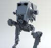
stu Posted March 10, 2008 Share Posted March 10, 2008 (edited) Michael and I were talking the other day and we got on about some of the car renderings that were going on recently, at which point I tried to coerce him into starting a WIP car buildup thread (I wanted him to make a DeLorean complete with a Mr. Fusion, but he wouldn't have it). At some point a finger was pointed in my direction, to which I confessed that I've had a soft spot for the F/A 18C Hornet fighter jet (or "Integrated Defence System", as the current contractor Boeing refers to it - whatever lets you sleep at night, I guess ) ever since I had the opportunity to sit in one and kick the tires in the early 90s. I've always wanted to do one, and I thought that it might make an interesting topic if I were to start from scratch and keep a journal throughout the process, so here goes. Here's a photograph: It turns out that neither the Defense Department or Boeing is keen on handing out the blueprints for this sort of thing (who knew?), so I had to scrounge to find the best that I could get (I'm sure that my google searches on the topic have put me on some interesting lists and I look forward to my next attempt to cross the border into the US ): It's not perfect, but it will point me in the right direction. I'll use it as a rough guide, but I will defer to the dozens of reference images that I was able to find online - thank you, digital cameras and airshows (there are some avionics enthusiast websites that feature a process they call a "walkaround", where they literally walk around an aircraft and document every inch with digital photography - the mother lode ). Next, I cleaned up the drawings and got rid of any unnecessary lines in photoshop: Some people prefer to apply images like these to textured polygons to use as an orthographic template, or to load them as background images, but I prefer to use the trace SOP to make a geometric template instead - I just find it easier to work with. One of the few bits of information that I was able to find were the basic dimensions for the aircraft - 56 feet long, roughly 15 feet tall, with roughly a 40 foot wingspan. Based on these measurements, I decided to establish a scale of 1 houdini unit = 1 foot. I also decided to establish 0 in the Y axis to be at the ground level if the aircraft was sitting on the ground, landing gear extended, and that the Z axis should run the length of the vehicle. 0 in the X axis is at roughly the center of the craft (for now - easy to change later if I want). I made a box to fit the outside dimensions of the aircraft, and using the trace SOP, imported the drawings as geometry and scaled and placed them appropriately: There's good news and bad news: the good news is that the aircraft is almost entirely symmetrical which will be a huge time saver, obviously. The bad news is that it makes the most sense to start with the fuselage - it's one of the more complex parts of the craft, and the most critical - if it's wrong, everything else will be as well. Next up, roughing in the body. Edited March 16, 2008 by stu Quote Link to comment Share on other sites More sharing options...
LEO-oo- Posted March 10, 2008 Share Posted March 10, 2008 Great idea! Thanks for the cleaned blueprint I had a check in my bookmarks - here are a link for more information: fas.org Quote Link to comment Share on other sites More sharing options...
AndrewVK Posted March 10, 2008 Share Posted March 10, 2008 hey stu! take a look at this book: http://www.aircraftresourcecenter.com/Rev1...absh/rev585.htm "...It simply goes into every area that a modeler might think of".....and this is TRUE!!! Quote Link to comment Share on other sites More sharing options...
mark Posted March 11, 2008 Share Posted March 11, 2008 (edited) looking forward to some insight into your process Stu.. and yeah its more interesting than cars =) (although Mr Fusion on a delorean would be cool) Edited March 11, 2008 by mark Quote Link to comment Share on other sites More sharing options...
stu Posted March 12, 2008 Author Share Posted March 12, 2008 Thanks for the links, and yes, I've seen links to that book - it sounds like it's the book to have when it comes to this aircraft. If I get to a point where I can't go any further, I might look into ordering it on amazon. After staring at a gazillion pictures for what seemed like hours, I decided to break the body into two major components - the central fuselage that contains the cockpit which starts at the nose and tapers almost all the way back to the engines nozzles, and the engine/air intake housings. I started with the central fuselage and made profile curves that followed the contours of the craft, in both the X and Y planes. I used nurbs so that I could get smooth curves, and tried to use as few point as possible to define the shapes so that I didn't introduce any unintentional bumps. I turned the level of detail in the viewport up to 10 so that the wireframe nurbs curves that I created displayed smoothly, even with so few points: The fuselage changes in nature along the length of the aircraft at about the point where the intakes for the engines are, and I decided to split the job into two pieces - the fuselage forward of this point, and back from this point. I started with the forward section, and created cross sections at locations that I thought were meaningful in some way. The cross sections are more of a rounded off square towards the center of the aircraft and become more round as they continue towards the nose. Next, I skinned the nurbs curves and then converted the resulting shape into polygons. Because this operation can have a tendancy to change the profile based on how many cross sections you provide (especially since I made a point to use as few cross sections as possible to maintain a smooth form), I had to make a few minor adjustments. I templated both the resulting polygonal cage and my original profile curves and made small adjustments to the nurbs cross sections until I was happy with the result: Because the cross sections started as nurbs curves before I skinned them together, I have the ability to not only change the polygonal resolution if I want to, but I can also use the pre-converted nurbs surface to creep any details along the hull should I decide to later. Here's what it looks like so far: rotation.mov More to come. Quote Link to comment Share on other sites More sharing options...
stu Posted March 13, 2008 Author Share Posted March 13, 2008 In order to continue extending the fuselage, I have to rough in the engine housings so that everything marrys together properly. Again, I started by identifying the rough contours by laying out some curves that follow the profile of the engines (sometimes you'll see my lines stray away from the wireframe blueprint - in a case like this, it's because I'm working around some of the blueprint inaccuracies): Next, I created cross sections to make the appropriate form, using as few curves as possible (again, because it has to be a smooth transition): I skinned them together, and converted them to polygons: The fuselage gradually tapers back between the engines, but the engines also come together with a central piece that creates a surface between them that, in turn, provides a surface for the tail end of the fuselage to diminish into: I created this by simply drawing a curve and extruding it. The intersection between this central piece and the engines themselves pointed out very clearly that my profile curves for the engines weren't right, so I had to go back and adjust the engine curves so that everything fit together nicely: With the central surface in place, I could now go back and extend the fuselage in a way that I new would sit properly with the back of the vehicle: As it stands, all of the pieces are created independently and are just shoved together - that's okay for now (although painful to look at ). I'm just trying to establish the relationships between the different surfaces so that I can move ahead knowing that everything is sitting together properly. When I'm happy with how it's working, I'll use these surfaces to create matching topologies so that I can build the smooth transitions between all of the surfaces that flow seamlessly into one another. Progress so far: rotation_2.mov Quote Link to comment Share on other sites More sharing options...
stu Posted March 15, 2008 Author Share Posted March 15, 2008 I took a break from the body of the plane (I tend to jump around on my models - not the best practice, but it keeps me interested) and did some work on the elevators today. Often when I'm working on something that has a very definite 2D silhouette, I'll make a guide using a bunch of curves and circles (you can take the boy out of Adobe Illustrator, but you can't take Adobe Illustrator out of the boy): Then I'll simply trace it with another Curve SOP: Because the elevators on this aircraft aren't flat, I have to create some interior geometry to allow for the bowing that will occur along the surface. I extruded the curve, Polybeveled the sharp corners, and used a Divide SOP to add a bunch of polygons to the interior: Next, I used a Magnet SOP to bulge the center of the elevator outwards: A couple of quick shapes and a Mirror SOP, and they're done: I have to say that I'm not all that keen on creating a rounded cross section this way with the Magnet SOP and philosophically it bothers me a little bit, but the change in elevation is so gradual on such a featureless surface that it should do fine. If the elevators weren't so simple in nature I'd probably create a bunch of cross sections and skin them together, etc., etc. If it still bugs me later I might change them, but good enough for now. Quote Link to comment Share on other sites More sharing options...
LEO-oo- Posted March 15, 2008 Share Posted March 15, 2008 Stu - nice! Thanks for explaining how you do it Quote Link to comment Share on other sites More sharing options...
stu Posted March 16, 2008 Author Share Posted March 16, 2008 My pleasure. ps. I'm so disgusted with myself for that last entry (Divide SOP? Way to phone it in, stu. :thumbdown: ) that I'm re-doing it - you'll see why when I post the update. Quote Link to comment Share on other sites More sharing options...
Marc Posted March 16, 2008 Share Posted March 16, 2008 hehe... I was wondering about the divide SOP, it seemed a little....er ... messy . I'm keen to see your other way. Thanks for doing this it's most educational. Cheers M Quote Link to comment Share on other sites More sharing options...
stu Posted March 17, 2008 Author Share Posted March 17, 2008 hehe... I was wondering about the divide SOP, it seemed a little....er ... messy Agreed - I debated as to whether or not I should be documenting do-overs and screw ups, but I think it makes it even more useful if I explain why I did something over and how I did it. I think that foresight is incredibly important in modeling, and well, hindsight is 20/20. My biggest problem with the Divide SOP in the example above is that it's: 1. Inefficient - it creates a bunch of polygons that "don't do anything". It arbitrarily created polygons without any consideration for the topology and so there was geometric heft that didn't describe anything. It's like taking a flat grid and dicing up one of the polygons for no good reason. 2. Ugly - it created a bunch of ugly little triangles around the perimeter of the shape that would make it difficult/impossible to bevel the edge later. Whenever I'm working on something knowing that I'm going to be beveling the edges (either geometrically or at render time with a crease attribute), I do my best to make sure that not only are the spans incoming to the edge fairly perpendicular, but that there aren't any polygons smaller than the bevel radius at the edge that is going to be affected. Luckily not all of my previous work is throwaway, and besides, anyone who tells you that redoing things isn't sometimes part of the process is a filthy liar. First, I created two curves that would represent the beginning and end of the new spans for the interior of the aircraft's elevator. I used the original silhouette as a guide (the outline is still right): Next, I skinned them together and converted them to polygons, making small adjustments to the original curves to make sure that the original outline for the elevator remained consistently within the same span of polygons: Next, using the Cookie SOP and the original curve for the elevator silhouette, I use a cookie SOP to remove the excess geometry: Much better. The geometry flows with the shape, all of the geometry is (will be) meaningful, and there aren't any ugly polygons around the perimeter. I could then apply the same Magnet SOP operation (thank you, proceduralism) that I did in the previous example: A couple of Polybevel SOPs and the add original elevator support, and we're good to go: There, I feel better already. elevator_animation.mov Okay, enough fooling around - back to the big stuff. Quote Link to comment Share on other sites More sharing options...
rdg Posted March 17, 2008 Share Posted March 17, 2008 Thanks for this! A question: Then I'll simply trace it with another Curve SOP: What does this mean? Do you curvesnap the new shape? Or really trace? Georg Quote Link to comment Share on other sites More sharing options...
stu Posted March 17, 2008 Author Share Posted March 17, 2008 Thanks for this! My pleasure. Do you curvesnap the new shape? Or really trace? Sorry about that, I wasn't being very clear - I just use the guides as a template and draw another curve with the "snap" option in the interface turned on. Quote Link to comment Share on other sites More sharing options...
stevenong Posted March 17, 2008 Share Posted March 17, 2008 Great stuff Stu! Your post ( and hopefully Michael's, if he updates ) definitely shows how one can approach modeling with blueprints etc. I might just try to do a simple car or something later on if I'm up to it. Yeah, I was wondering about the first set of elevators you did with the Divide SOP too but glad you re-worked it & they look much better. Thanks for taking the time & keep the updates coming! Cheers! steven Quote Link to comment Share on other sites More sharing options...
kumpa Posted March 17, 2008 Share Posted March 17, 2008 Hi stu, i dont want to sound smart, but what about giving good old Crease SOP a chance ? I believe it would perhaps be possible to describe elevator form with something little more complex than box and careful crease value adjustments. k Quote Link to comment Share on other sites More sharing options...
stu Posted March 18, 2008 Author Share Posted March 18, 2008 Hi stu, i dont want to sound smart, but what about giving good old Crease SOP a chance ? Subdivision surfaces and crease weight attributes are definitely a possibility, I just tend to lean towards geometry when I've got a very specific target because the feedback is instantaneous in a WYSIWYG kind of way. Quote Link to comment Share on other sites More sharing options...
cellchuk Posted March 20, 2008 Share Posted March 20, 2008 it looks like it's gonna be a great model when it's done. very nice post :thumbsup: cheers Quote Link to comment Share on other sites More sharing options...
stu Posted March 20, 2008 Author Share Posted March 20, 2008 Thank you. Update coming soon. Quote Link to comment Share on other sites More sharing options...
stu Posted March 22, 2008 Author Share Posted March 22, 2008 (edited) I want to focus on the body again so I decided that I needed to lock down the level of detail in the nurbs conversions and line the spans up between the main fuselage and the engine housings. This is how I last left it: It's a mess. Not only don't the geometric spans line up between the independent pieces but they are also unevenly spaced, which will make connecting them and creating smooth transitions between them difficult. I have to reorganize the spans so that they line up where the separate model pieces are going to eventually come together. First, I created a box with the same dimensions as the combined separate aircraft pieces. The Box SOP has "divisions" turned on with a number of divisions that I thought would work well (the nose has been excluded on purpose - it's spans don't have to be unified because it doesn't connect to anything else, and it's form is so specific that I'd have to at least triple the number of evenly spaced divisions in order to maintain it's original shape. It's fine the way it is.): Next, using the Box SOP divisions as a guide, I used multiple Carve SOPs (set to "Extract") and created evenly spaced cross sections with the original nurbs' surfaces. The main body has half as many cross sections as the engine housing because it's a broader and smoother shape and could be accurately defined with fewer curves. It's okay that one section had twice as many carved spans as the other, as long as they are all evenly spaced, line up properly, and are a an even multiple of each other - I can even it out when I convert them into polygons by converting the engine section to resolve at half as much detail: Here's a rotation: carve_rotation_comp.mov Using the Skin SOP, I skinned the curves together, (I skinned the main fuselage and the engine housing separately) and then converted the nurbs surfaces to polygons at a level of detail that I thought would suit the model. The two separate pieces have spans that line up along the length of the aircraft now, and the spans are evenly spaced: I attached the nose, and here's where we are: This exercise didn't do anything to add any extra detail to the model, but in doing so I've made upcoming progress much more straightforward. Edited March 24, 2008 by stu Quote Link to comment Share on other sites More sharing options...
stu Posted March 24, 2008 Author Share Posted March 24, 2008 I'm going to continue with the body and do some work on the leading edge wing extensions that start at the wings and taper along the length of the fuselage: I think that it's always important to start with what you know and extrapolate from there. Using the reference that I've gathered (and referring to the drawings that I'm using), I can establish where the extensions join the body, and what their profiles look like from the top and the side. I started by drawing a nurbs curve (using as few points as possible so that it is as smooth as possible) from the side indicating where it will attach to the main fuselage: Using a Ray SOP, I projected the curve onto the surface of the fuselage: Next I created a curve profile and, using the Sweep SOP, swept it along the curve that was projected onto the surface of the aircraft, and then skinned the profile curves together: Using two nurbs curves, I outlined the shape of the extension from the top view: And I skinned them together... ...and ran into the same issue that I had when I was making the main body pieces - I've got uneven spans that won't line up with the main body spans when I try to attach it with smoothly where it meats the leading edge of the wing. So I took the same approach that I did with the body - I used the same divided Box SOP that I used in the previous step, and using a Carve SOP, I created evenly spaced cross sections that will line up with the body spans: I skinned them together, did some touch up work modeling, and I have topology matching between the main body and the wing extension: You'll notice that the spans don't synch up with the fuselage at the very tip of the extension - it's because I had to add extra spans in order to create the shape the way that it was intended. It's not going to cause any problems because there isn't a smooth transition between the extension and the fuselage at that point and the two surface will simply intersect. I can live with it. Next, using the Ray SOP again, I projected the surface that I had just completed onto the skinned nurbs surface that I created earlier along the length of the aircraft: At this point I did what seemed like hours of fiddling with both surfaces to make sure that everything was lining up as it should be. The next step is to smoothly transition the leading edge extension into the engine housing. This is how it looks now: Gross. It should smoothly transition into the engine housing, and step down to the wing support, like this: I started by deleting everything that I new would be thrown away which was the geometry that was occupying the space that would eventually become the transition. I drew two curves that represented the in and the out point of the upper part of the transition: Next, using nurbs curves because I wanted the transition to be smooth, I drew what would become the "rails" of the upper part of the transition. I was careful to be sure that the curves reflected the tangencies of the incoming surfaces so as to smoothly transition properly: In keeping with the evenly spaced spans that I had already established for the main fuselage, I uses a Resample SOP to resample the Nurbs curves so that the transition would fit with the rest of the model properly. Finally, using the Skin SOP, I brought it all together: I did the same thing with the lower step to the wing support, and using the engine housing profile as guide, created a curve and used a Rail SOP to join the surfaces together, respecting the design of the aircraft: So here's where we are: rotation_comp.mov Getting there. Quote Link to comment Share on other sites More sharing options...
Recommended Posts
Join the conversation
You can post now and register later. If you have an account, sign in now to post with your account.
Note: Your post will require moderator approval before it will be visible.