goshone
-
Posts
41 -
Joined
-
Last visited
goshone's Achievements
")


-
I am also interested in something like this. Every time I try to use IK vopnet, all of the rest angles seem to be disregarded. Perhaps full body IK is the solution. I saw that in another post (procedural creature)
-
I am able to select a node in the network editor with python very easily. The problem I am running into is how to cause the parameter window to update based on this selection. There seems to be different levels of selection. When selecting through the UI (left-clicking on a node), the node turns deep yellow, and the parameter window (PW) updates. When you shift select with the mouse, the last selected becomes deep yellow, and the previous node is outlined in a lighter yellow (this is the sort of selection that is produced by calling node.setCurrent( 1 ) or node.setSelected( 1 ). If you click off a node in the network editor, you essentially deselect all the nodes, but the last selection remains in the PW, and the relative node has a slight white outline around it, I guess indicating the PW relationship. I am trying to create a new node and have it become selected with the PW reflecting the new object. Does anyone have any tips on how to accomplish this easily without querying too much of the UI panels? Thanks Josh
-
Here are my opinions of nCloth vs Houdini cloth (FEM solver) nCloth Pros: 1. really fast 2. stable 3. integrated into Maya, which is our software of choice 4. large freelance talent pool 5. flexible as a cloth, skin, soft body, or rigid body solver Cons: 1. doesn't scale well - higher resolution meshes require tweaking to get similar low resolution results 2. doesn't natively allow for high-quality tearing effects 3. integrated into Maya ;-P (limited effects integration) 4. Complicated parameters, and a lot of them Houdini cloth Pros: 1. Integrated into Houdini, works well with other effects, fields, and known techniques (sop solver, sop modifications, etc.) 2. Scales predictably (supposedly) - hi resolution meshes behave similarly to low resolution meshes. 3. Robust... Allows for tearing, deformation, rigidity, etc. 4. Streamlined parameters, not much to tweak Cons: 1. Slow (currently) - trying to see which parameters to turn down to improve performance without losing accuracy 2. Not very stable - Again, still learning the new solver, so I have to see which parameters do what on the solver. 3. Streamlined parameters, not much to tweak (also a pro, but with experience, this may not be as big of an issue) 4. Not production proven That is my list currently. If there are any other opinions regarding this, please share.
-
While I agree with the technique of writing geo to disk as often as possible, this is more of a question of efficiency, especially when having to fight for render resources or battle with time constraints. While it makes a lot of sense to write sim data, then extract the geometry as needed to write them out separately, there isn't much, if any, time savings with that approach. I found it taking entirely too long to read the .sim files and extract the RBD geometry. There is a huge amount of time spent on transforming the RBDs. It works, but it seems like it should not take that long to read data and apply it. Another concern is any slight mismatches of the simulation. I know Houdini is stable and predictable in this area, but I would hate to encounter a slight difference from sim to sim because maybe the render farm picks up a slightly different processor type with slightly different floating point calculations. I am not sure if this is still a problem as it was years ago.
-
I had submitted the original ticket for this only a few days before this thread appeared, and after testing with the 288 build, I agree that it is improved, but still far from perfect. This bug fix seems to only affect the cloth self collisions, and does nothing for handling the collision with other objects, like a static RBD object for example. EDIT While doing further testing while writing this post, I can verify that disabling the volume collisions on the static RBD does make a difference in the collision distance. That's a good find there. I am continuing to test with this new build, trying to replace nCloth as the go-to method for CG clothing/skin/softbodies.
-
With the new dynamics workflow in Houdini 13, there seems to be a tendency to simulate many things in the same DOP network. In fact, this is the second time this issue has come up, and only the second project in H13. Imagine RBDs falling into a flip simulation, (ice in water if you will), and you want to write out both the ice geometry and the water simulation geometry (flip points). What I ended up doing in this case, is write out the .sim data once, then extract the geometries and write those out in a separate process. This technique was clunky, as it resulted to a file node in-line in the DOP network, leaving a huge room for error. The second case deals with DOP particles, created using the new H13 particle workflow. I have an RBD simulation of fractured geo, and I would like to add some small debris particles and smoke. Should I do the sims in stages? (RBD -> particles -> pyro) While it makes sense to do the pyro as a separate stage, since it would slow down the iterative process and dialing in the behavior of the RBDs, it would be awesome to be able to sim it once, producing 3 separate geo sequences at the same time. Does anyone have thoughts or solutions to this? Thanks in advance. Gosh
-
Just had this happen today, now I'm in this thread. Using H 12.5.376 on CentOS 6.2 (not sure about the nVidia driver).
-
The reason nothing happens when you paste the script is because all this script is doing is defining a procedure, which you have to call to execute. I didn't have much luck pasting the code into the python shell because the formatting got thrown off in the previous post, but you could save it as an external script in your python path, import it (eg. import simToKeys as stk ) and select your objects and run the script (eg. stk.simToKeys() ) Now this is hard coding the name of the DopNetwork, so modify for your own uses of course. I'm not sure why the file isn't working, but that has the script contained in the file via the python source window (houdini python session), which is rather convenient for changing names of the autodop for example, but beware of the bug I mentioned previously. good luck!
-
So I was able to get this working with some tinkering. The script was relatively easy, simply needed to work out the loops. A bigger issue was how to get the object to transform correctly before and after baking the keyframes. The solution was to set the initial state of the RBDs to be the transform values of the original objects, and uncheck the "Use object transform" option. This would start the RBDs in the right world space so you get corresponding keyframe values. The I had some strange bug that caused the houdini python session window to not run the script properly. I included a file which has the script in the python session window. You just need to delete the last comment and accept to get the script to refresh for whatever reason. Then just select your objects and run hou.session.simToKeys() in the python terminal. I didn't include the writing of the chan files, but I think you could easily add that, and encapsulate it into a better external script. cheers G1 ps. here is the code def simToKeys(obj_to_export = hou.selectedNodes()): DOPNET = hou.node("/obj/AutoDopNetwork") SIM = DOPNET.simulation() F_START = 1 F_END = 100 frm = 1.0 while frm <= F_END: hou.setFrame(frm) for obj in obj_to_export: t_parm = obj.parmTuple("t") r_parm = obj.parmTuple("r") for t,r,i in zip(t_parm,r_parm,range(3)): ## Keyframe object## keyframe_r = hou.Keyframe() keyframe_t = hou.Keyframe() r_parm[i].setKeyframe(keyframe_r) t_parm[i].setKeyframe(keyframe_t) dopOBJ = SIM.findObject(obj.name()) dopMatrix = dopOBJ.transform() obj.setWorldTransform(dopMatrix) ### delete this comment ### frm = (frm+1) rbd_xfer_v01.hip
-
I just tried this, but things came out a bit toooo blurry for my tastes. It could help in some cases tho. I think it is good to know there are options to get the look you want. After further testing I have found that this artifact is most noticeable where heavy density meets no density, like the leading edge of an expanding billow of smoke. Higher resolutions seem to help, as do varying up the velocity (via fields or turbulence) as much as you can without breaking the look you are going for.
-
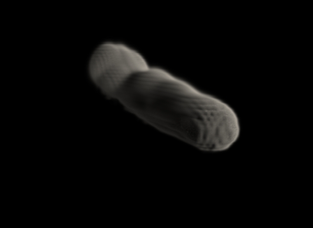
Something that is throwing me off, whether it's a feature or a bug, is how the expanding volume container is displayed in openGL. I have included a playblast of my sim, which looks quite nice in the render so far. But looking at the chunky volume, I was very concerned of the final images. Seeing how the volume is nicely defined towards the beginning of the sequence, I think it is not actually adding addl voxels in GL preview, but expanding the existing slices at the beginning to describe the increasing volume. The best analogy I can give is this behavior is similar to metaballs display, where the polycount is initialized at some point, but as your metaball mesh expands, it doesn't actually add more polys to account for this, resulting in a very coarse mesh as the size and complexity of the metaball cluster increases. Hopefully that all makes sense. build_debris_fxSetup_v008_playblast.mov build_debris_fxSetup_v008_mantra.mov
-
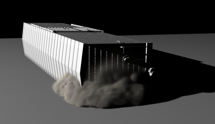
True, it seems that it is a combination of techniques to get the most out of these solvers. The source of the volume is fairly important IMO, and the results are better when allowed to be moved around the container by velocity and forces rather than collisions or emissions. This can be seen with obvious grid artifacts around the emission point which get smoothed out over time during the simulation as the volume evolves within the container. I may have had overestimated things a bit too much, and expected beautiful low res simulations straight out the gate. That being said, the performance from H12 is stellar, and that is without harnessing the GPU/openCL side of things. There are a couple of render tests attached below, a lower resolution sim (v001c) which had some disappointing line artifacts, and another sim (v001d) with half the voxel size (so basically 4x the voxel count) which is drastically improved, although it may be hard to tell from the quicktimes. These have no material assigned, so that should only improve things, especially with some noise and adjusting the edge falloff. Anyway, just some observations... still continuing to test out this awesome version release. build_debris_fxTest_v001c_mantra.mov build_debris_fxTest_v001d_mantra1.mov
-
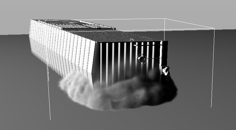
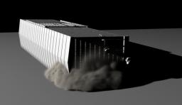
So I have been trying further with this, on more of a real world shot. As much as I try, I am still unable to get rid of this grid issue. It is clearly visible in the viewport, and can minimize it as described above, but then the smoke becomes very blurry, and it still is perceptible. It has me wondering if I am simply doing something wrong. I initially thought it had to do with the source geo being only a poly shell and not a full volume. I closed the geo and used iso-offset to become a solid volume, but that did very little to fix the problem. The source is moving which can always be tricky because of substeps and stamping, but even emitted density becomes very striated with these grid lines. So is my box simply too low resolution? The box in the image is about 125x75x125, which seems reasonable. I am just worried about the visible lines in the viewport, as they translate directly to the renders. In this particular scene, which I am unable to share at the moment, I am using the smoke solver with some added noise applied to the source (density and velocity noise) and some turbulence in the container, both of which are aimed at moving the density around and blur these grid lines. Not having much luck though. Any assistance would be appreciated.

-
Yes, this helps quite a bit in fact. That seems more along the lines of what I would expect from older versions, as well as from other software. It also seems that there needs to be a bit more care put into the sims to break up the regular-ness. After looking at the beautiful results from some of the pyro fx tab buttons, I realized that adding some noise to the source or the container (or both) produces very nice simulations even at low resolutions. Another thing I noticed is that the volumes look much better WITHOUT any material assigned to it. When you attach the billowy smoke shader, it multiplies the density by 10 (by default) exaggerating the aliasing. I will continue to investigate these and post any additional tips or info I glean from the process. If there is any advice on solver or shader selection (smoke vs. pyro) and the pros/cons of each I would be very interested to hear.
-
Is anyone else getting these weird grid artifacts in your smoke sims? I just started diving into H12 and testing out some smoke simulations. After working on them a bit, I kept noticing very prominent grid artifacts in the viewport. I thought they would go away during the render, but they persist, and ruin the look quite a bit. It is minimized but still visible with higher resolutions. I went back to H11 and this doesn't seem to be a problem in that version. Is this something common among other users? I have attached a sample scene and image. build_debris_fxTest_v001.hip