zeekindustries
-
Posts
30 -
Joined
-
Last visited
Recent Profile Visitors
3,142 profile views


zeekindustries's Achievements
")
Newbie (1/14)
1
Reputation
-
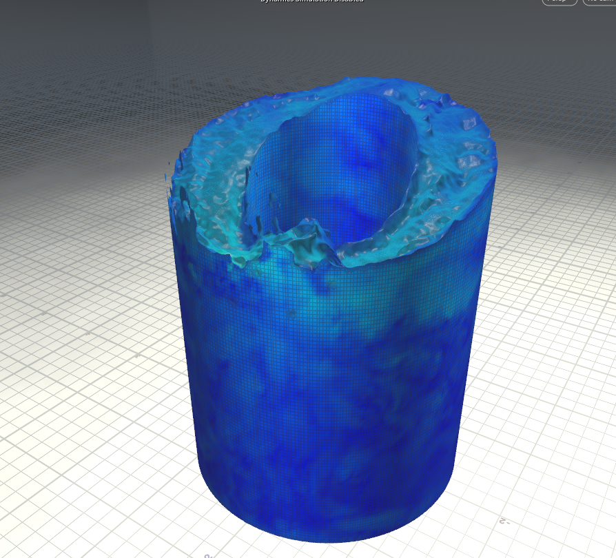
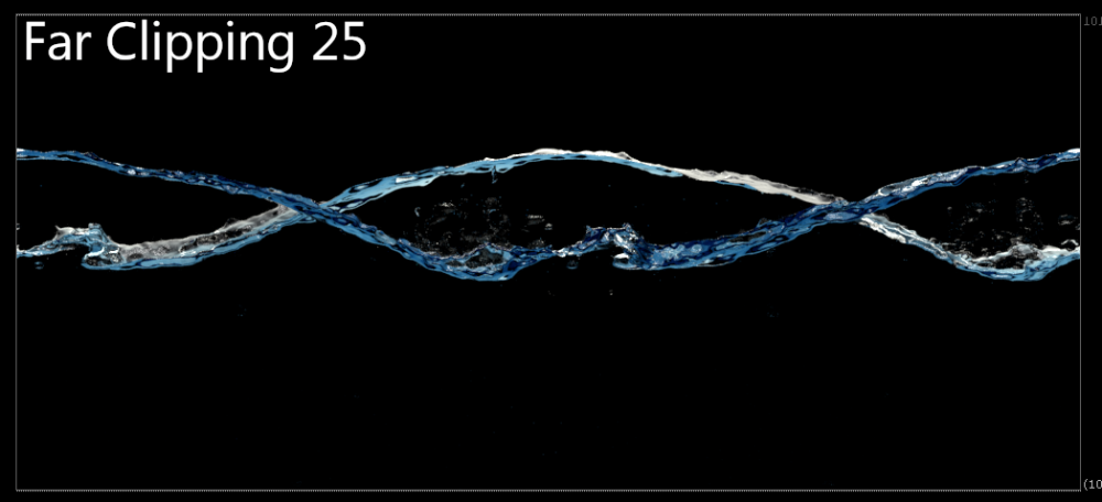
 Hello wizards! I am doing some glass renderings, and for a very specific case I am facing a problem that could be potentially solved by limiting how far a refraction ray should travel. Like, if the next level of ray depth already travelled a certain distance kill it and return the color of the environment for example. This is because there are some cases where my object could refract itself which is something desirable but only at a certain distance. I found on the documentation that there is a maxdist for the RayOption on the trace() and refractlight() function, but I have no idea how would I go into using it or building the shader. The render configuration right now is using a custom lens that at the beginning of the project meant for it to let us see the other side of this water cylinder, I can hide a portion of it by limiting the far clipping, but then of course parts that are inside the refraction will still be visible, that's why I'd like to be able to kill the refraction rays if the have travelled a certain distance since self refractions are still desirable for the surface's top part. So far what I would be trying is a combination of manual masking and using the RayLevel image plane that gives me a little of what I need but still not the perfect solution. Certainly a bit of help regarding manipulating the rays within Mantra would be of huge help.
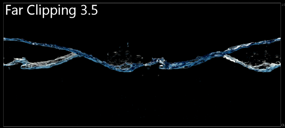

-
Hello Wizards! I have a quick question for all VEX samurais over there regarding as the title implies the clipping planes of a lens shader. So far I understand and am able to manipulate the P and I (direction) of where the rays are shooting, but I'm trying to find a way to modify the far and near clippling planes of my render. So, my concrete question is: what is the CVEX declaration of the near and far clip plane in a lens shader? I mean it should be something in the lines of: export vector P = 0; //Ray origin in Camera space export vector I = 0; //Ray direction in Camera Space export int valid = 1; //Whether the sample is valid for measuring //tried this as referenced here: https://www.sidefx.com/docs/houdini/vex/functions/orthographic.html but no dice export float clip_near Thanks a lot for reading Cheers!
-
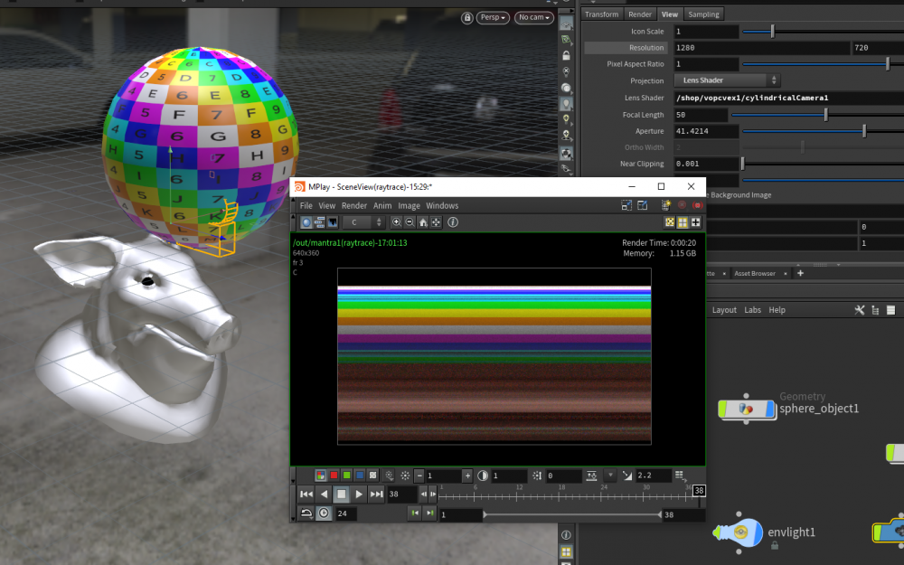
Hey guys! @Iskander @konstantin magnus So I managed to get the CVEX working on newer versions of Houdini, turns out that the CVEX operator, becomes a CVEX VOP that can go inside a CVEX Shader Builder operator inside the shop context. Said that, I was able to follow Paul's instruction to get an idea of how the lens shaders should work, but now I'm a little bit stuck on reproducing the inverse panorama. I'm getting something like this at the moment with the following code on my lens shader: #pragma opname cylindricalCamera #pragma oplabel "Cylindrical Camera" #pragma hint x hidden #pragma hint y hidden #pragma hint Time hidden #pragma hint P hidden #pragma hint I hidden #pragma range r 0 10 #pragma range h 0 10 #include "math.h" cvex cylindricalCamera( float x = 0; float y = 0; float Time = 0; export vector P = 0; //Ray origin in Camera space export vector I = 0; //Ray direction in Camera Space export int valid = 1; //Whether the sample is valid for measuring //R and H of cylinder float r = 10; float h = 4; ) { vector pos = P * PI; P.x = sin(pos.x) * r; P.z = cos(pos.x) * r; P.y *= h; I = normalize(P * {-1 , 0 ,-1}); } For what it seems, looks like the sample position is not really changing at all. Some ideas would be greatly appreciated! Cheers!
-
Hey guys! Glad to see there is a little bit of light to this setup. I am currently facing the exact same problem, where I need to render that inverted panorama. Wanted to ask if you guys were able to figure out how to define a CVEX lens shader in newer versions of Houdini, I am a little bit lost right now because at is noted the workflow for CVEX operators changed, and for what I have researched seems that maybe I am on the wrong direction. In some part of the documentation says that I need to make first an .vlf file and then turn it into an HDA, that is for Solaris/Karma which I don't think is what I need. Seems that it should be simpler than that. Thanks a lot and sorry for the trouble! Cheers!
-
Hold Attribute Value with Solver
zeekindustries replied to zeekindustries's topic in General Houdini Questions
Thank you very much for the guidance and the help, I understand much better know how the workflow should be prepared for this. I didn't thought about the initialization of the value, so I'll keep in mind that for the next time I run into this. Really appreciate the time and examples, cheers Srdjan! -
Hey guys! I'm trying to wrap my head around the solver sop. I have an alembic geometry that needs an attribute for the frame any point started changing position. What I tried was, inside a Solver SOP, appending a Point VOP where I subtract the rest position from the new one, compare the length of that delta and then write the frame on an attribute. The test and such works fine, but then my frame keeps changing, which I understand that it happens because I haven't figured a way to stop the value from changing. What I'm trying to achieve is to do a color ramp on the points by the attribute that tells which frame started moving. Any help will be very much appreciated! 20200316_CubeAnimation.rar
-
Hey everyone! I'm testing the Vertex Animation workflow which has been proved to be a great solution to our pipeline, but had run onto a somewhat relevant issue. Everything from exporting to setting up the material and textures has gone smoothly. The problem in here is that the camera culls the object if you are too close to it. I'm thinking that it may be related to the bounding box of sorts, but I haven't been able to figure out the problem. Here's an illustrative gif of what's going, As you can see the selection outline shows that the object is still active within the scene, but rather is no longer drawn. Anyone has come across with this? Any help would be much appreciated. Cheers!

-
Hey everyone! So I'm trying to export a flip surface that I stitched to a cube in order to get some depth for my water shader in Maya to work properly. Everything is working fine until I get to the point that I need to transfer the velocity as a vertex color set. For now if I bake the color in just the surface it works but as soon as I try to do it with the stitched cube some frames are missing the color within Maya. The message that I get is // Warning: Color sample size != num face vertices // The way that I'm doing it right now is that I drop an AttributeCreate run it in Vertex as a Float 32 bit Color attribute of 3 componentes, pointing to the @v attribute from the fluid and export it. As I said, I get some frames with it some without it, so I'm not sure if I'm missing something on my export step. Any direction on how to solve this will be very much appreciated, thanks a lot!
-
Hey guys! Thanks a lot for the input and the quick reply, because of the difference in hours, I just got the time to check them out. I really appreciate your help, really getting me into the right path. Now it's more clear, I thought that the points created from the 'Points from Volume' should have some extra attribute created as velocity and such, but I can see that they only need to be generated and lying inside the bounds of the Flat Tank. Definitely owe you guys a beer sometime.
-
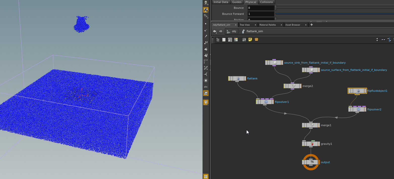
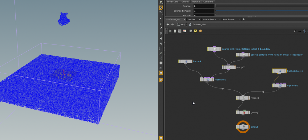
Sure, here's a little example of what I want, right now, I'm using a flat tank, but then the same would apply if I wanted to use a wave tank, the problem is that I don't quite understand how to make the pig head be part of the same FLIP Object as the tank or viceversa. Thanks guys! tankAndFluiObj.hipnc
-
Hey everyone! I want to create a sim with a fluid created from an object and pour into a Flat tank sim, but I'm failing to make them merge into the same FLIP object within DOPS. Flat tank and Fluid from Object will give me a different FLIP solver that of course will not interact, so I'm not sure how to make the FLIP object become part of the same sim. It'd be very helpful if someone could point me in the right direction, as I'm looking into the forums and can't find something close to what I need. Seems to me that I have to make the fluid from object merge in some way into the OUT_Pts from the flat tank but I'm not sure how to feed the correct information onto the merge to have it recognized as valid FLIP data. Any guidance will be very much appreciated, thanks!
-
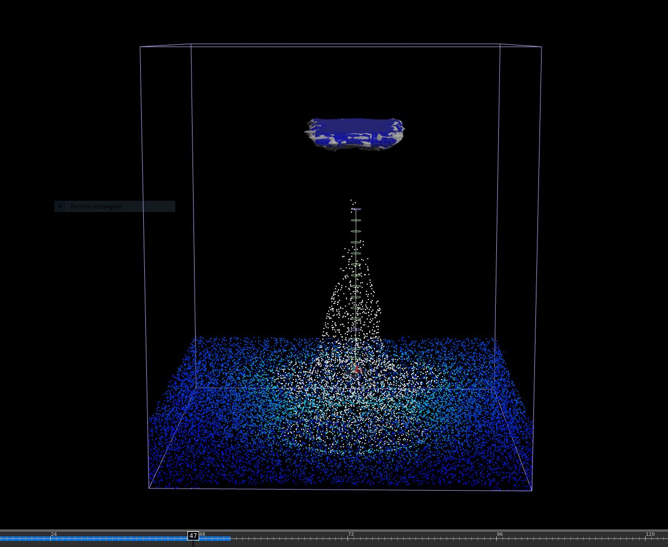
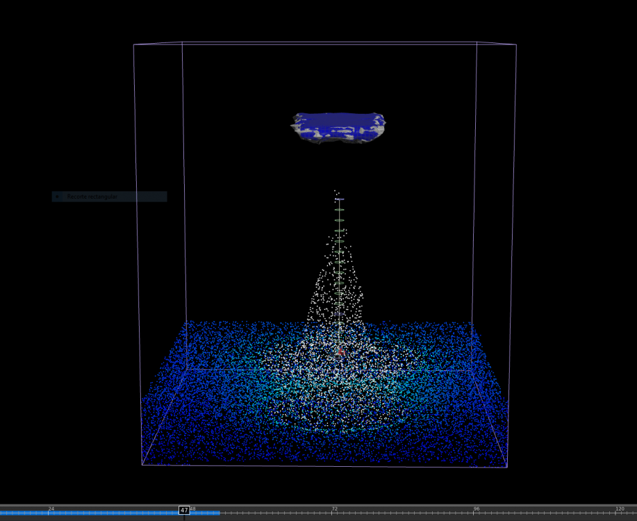
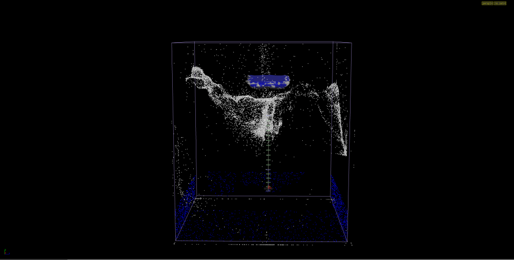
Hey everyone! It's been a while since the last time I posted here because I was a little off from doing FX, but now I'm back on learning and stomped on some difficulties trying to do some collisions, flip and RBD simulations. The problem is that everything goes fine until a certain frame and the next one everything is exploding. I'm not sure if I'm not feeding the proper collision to the simulation or if the external forces override the movement of the particles rather when collision with a geometry takes places. A brief description of what I want to do is to achieve somewhat this kind of effect: -Water being pulled updwards, colliding with an object and continue the fluid simulation motion from there I'm attaching the .hip, some screenshots and a reference for what I want to do. Thanks a lot for taking a look and if someone can point me in the right direction I will be very grateful. Cheers! kamigawa_v002.hip
-
Thank you so much for the help!!! I found it very usefull. Thanks a lot Pradeep, your file illustrated very well how it could be done, I wasn't aware of the bind node inside the VOP networks, very handy indeed. Cheers!
-
Hello! I would like to ask how would you wire a POP VOP in order to create a ramp to control the scale of a particle over it's lifetime. What I want to achieve is something like this: Lifetime = 0, Scale = 0 Lifetime = 0.5, Scale = 1 Lifetime = 1, Scale = 0 I'll really appreciate if someone could help me, I'm kinda new to VOP's so It's something that I can't seem to sort out. Thanks a lot!
-
Hello guys! I'm new to the pyro solver and I have understood somewhat the basics of the solver, but for now what's keeping me hitting on a wall is how do I set the initial values for the simulation. I have exported a .bgeo using a DOP I/O dop with the fields that should be needed (temperature, vel, density, fuel and heat), and pointed to them on the smoke object dop but can't figure out how to map the heat on that initial state. I'm giving you guys the link to my .bgeo file if anyone can help me out. Thanks a lot everybody! https://dl.dropboxusercontent.com/u/19910308/Seq_003c_fire_Initial_v01.bgeo