Leaderboard


Popular Content
Showing content with the highest reputation since 02/07/2026 in all areas
-
New video on how USD Render Prims work and how to use the new Render Pass prim.2 points
-
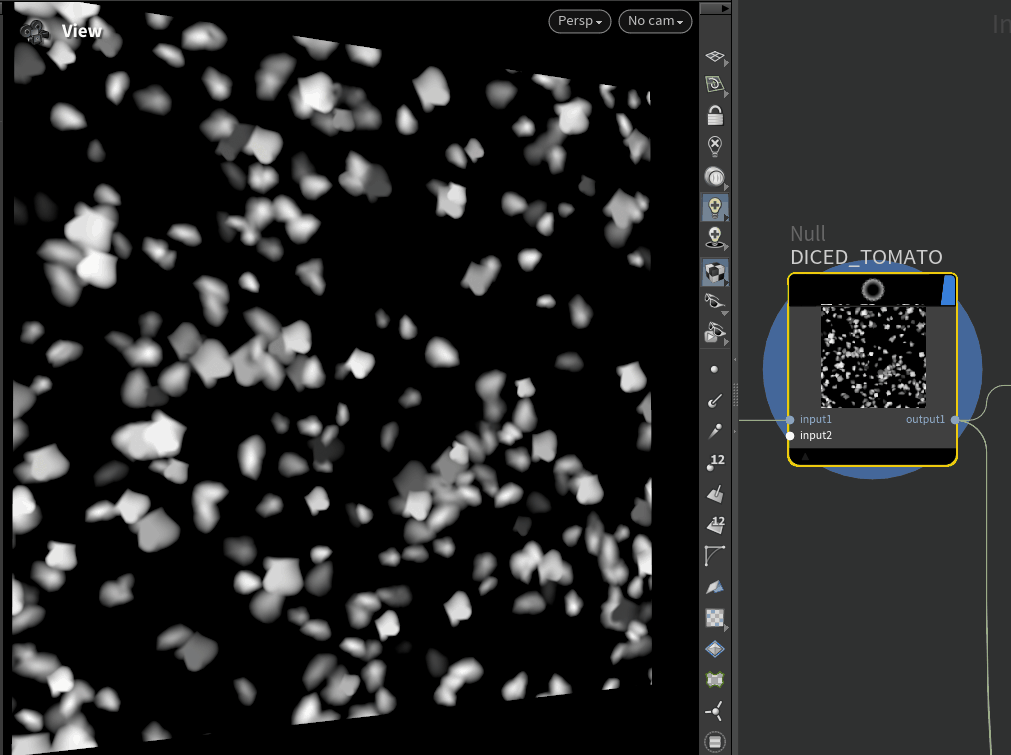
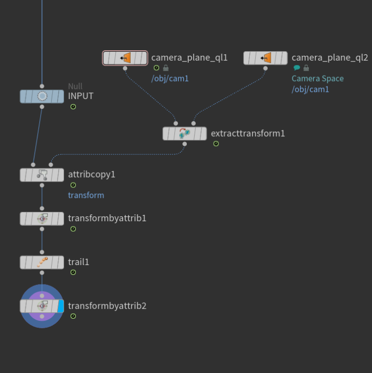
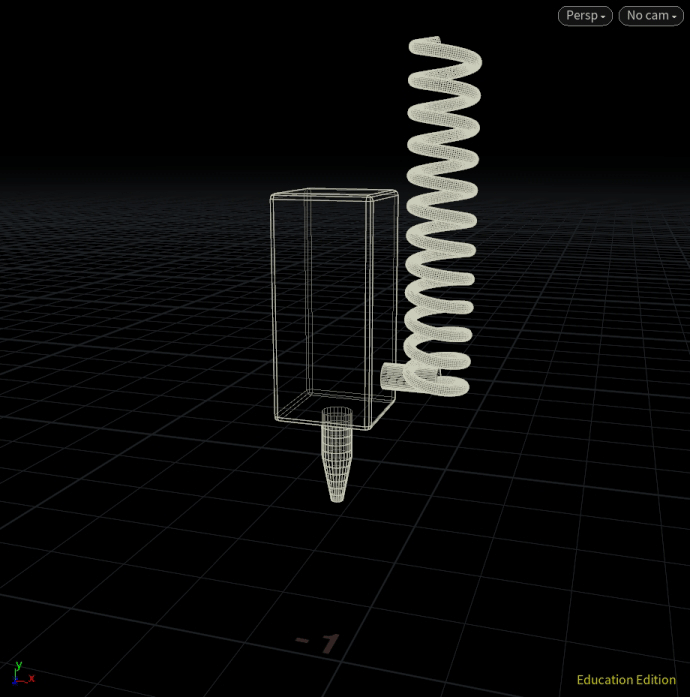
Yep, kinda like this but devil's always in the details and you have to account for oversampling (timestep) of the sim, especially with age accumulation. You only need the Gas Field VOP to use increment age by the timestep using density as a mask btw. Everything else can be done with Gas Calculate (tends to be faster than Gas Field VOP for simple stuff). - initialize age field at sim start channel matching fields from Smoke Object DOP - increment age by timestep using density as a mask (unless you want to add time to all voxels, up to you). - Keep source field around (need to remove "source" from clear fields in Source Volume DOP) - create temporary agetemp field and add source field reset to be constant timestep (you can't count on source always being set to 1) - Add agetemp to age - advect age I haven't really thought about the best order of things: - when to add agetemp to age. Before or after advection. Open to suggestions/advice. See the attached hip file for an attempt at this. age_field.hip This temp field is pretty hard to read in the viewport when it is visualized as it is kind of like density but counters velocity (to be expected as faster areas should be darker when visualization set to greyscale for age). it looks to be kinda correct. I hope...2 points
-
Thanks a lot, I really appreciate the feedback. You are right, there is a lot of things happening now around AI, ComfyUI, GitHub tools and free stuff too. My main goal with Houdini AI Assistant is not just make another AI tool, but to build something that feels native in Houdini and helps more direct in procedural workflow. AI texturing / projection in COPs is definitely a interesting direction, and yes I agree it can make the product stronger. Right now I focus more on making the base solid first, then add more practical Houdini specific features step by step. Thanks again for your thoughts.1 point
-
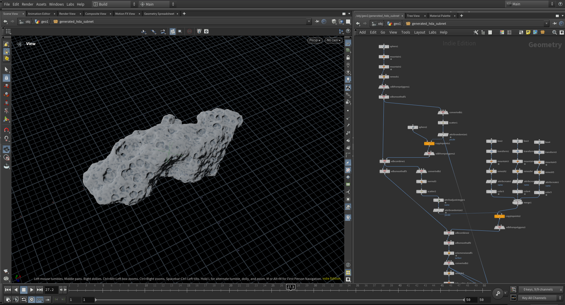
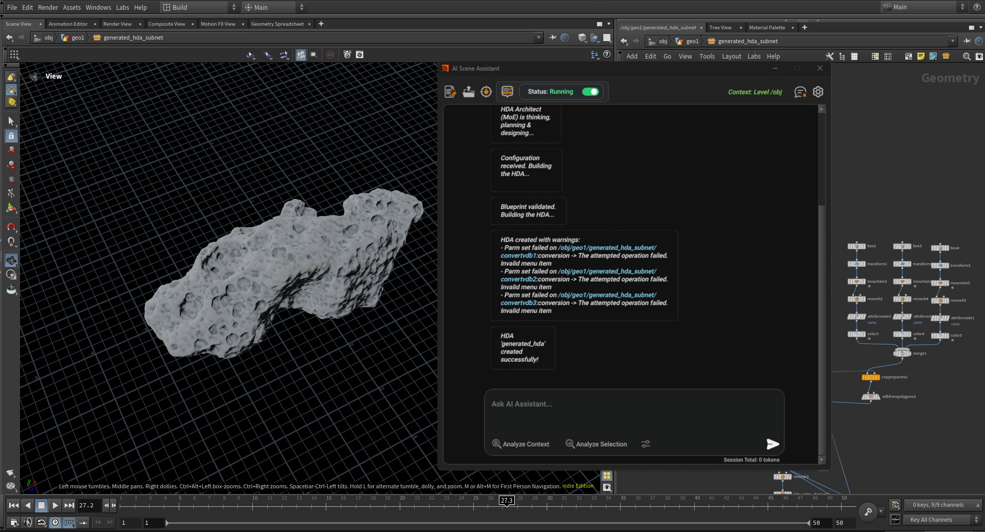
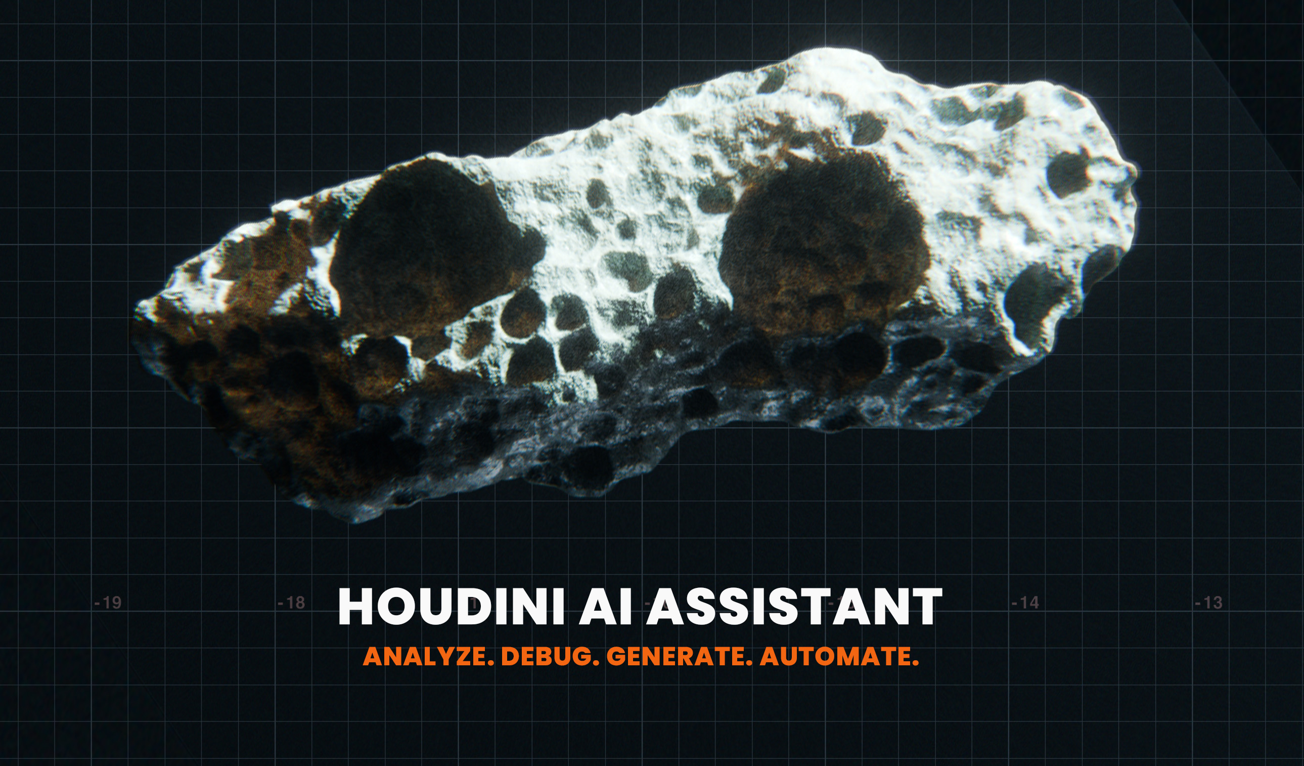
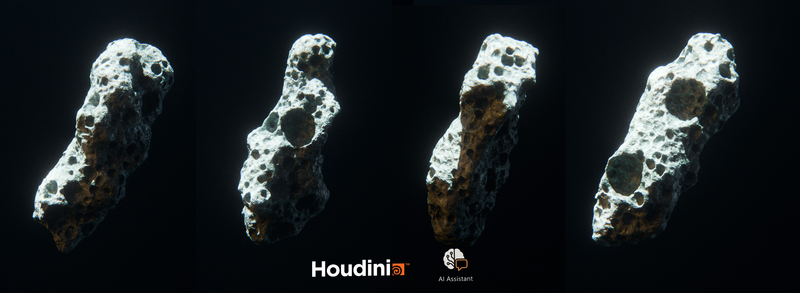
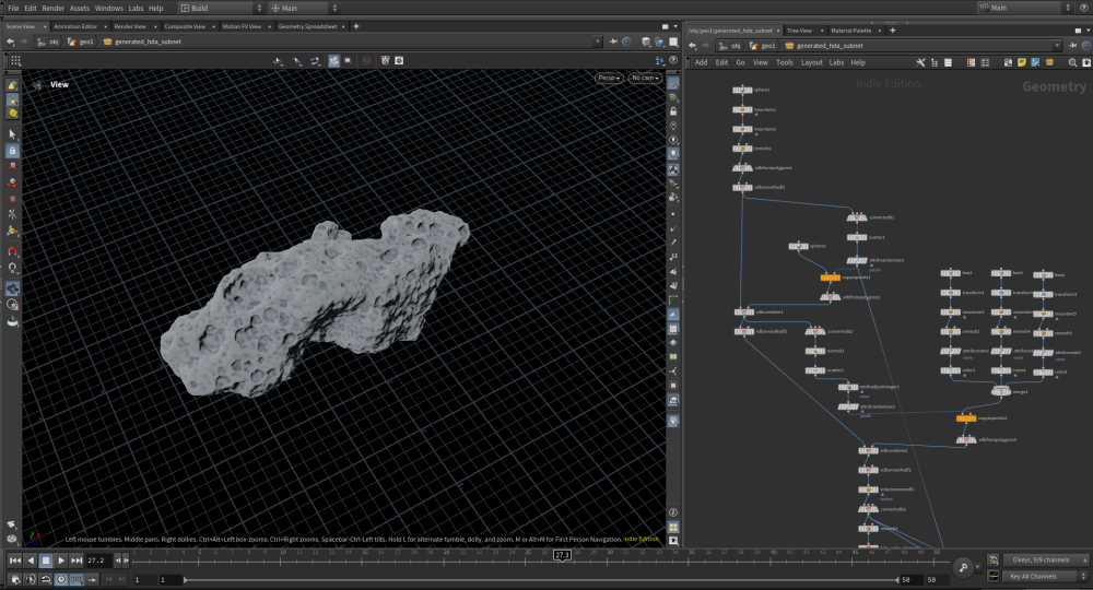
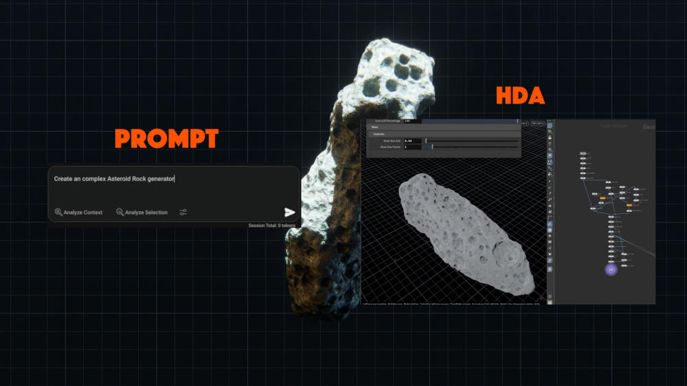
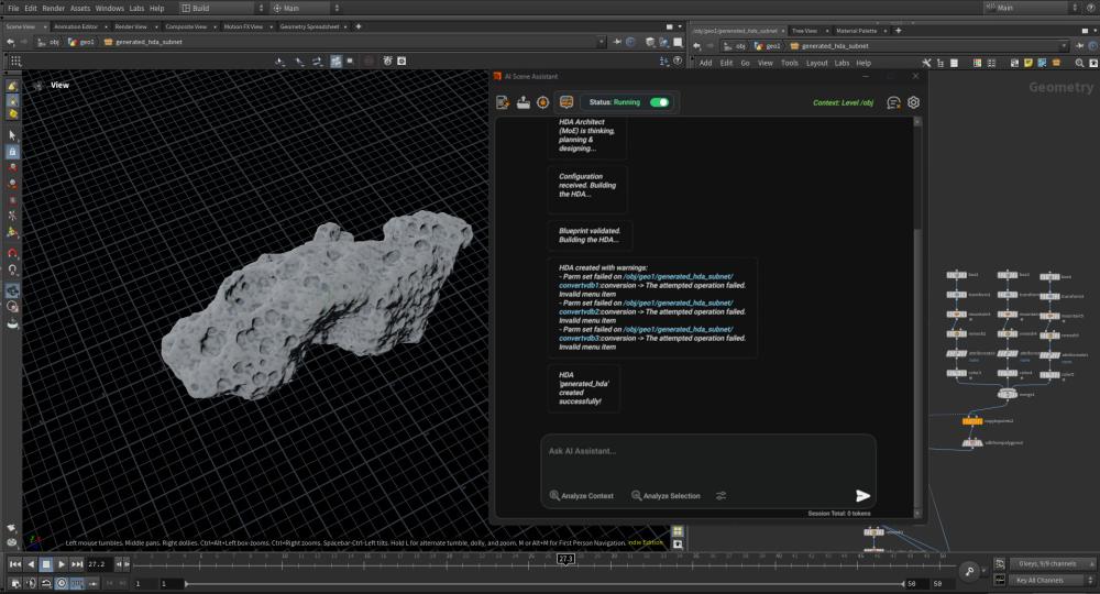
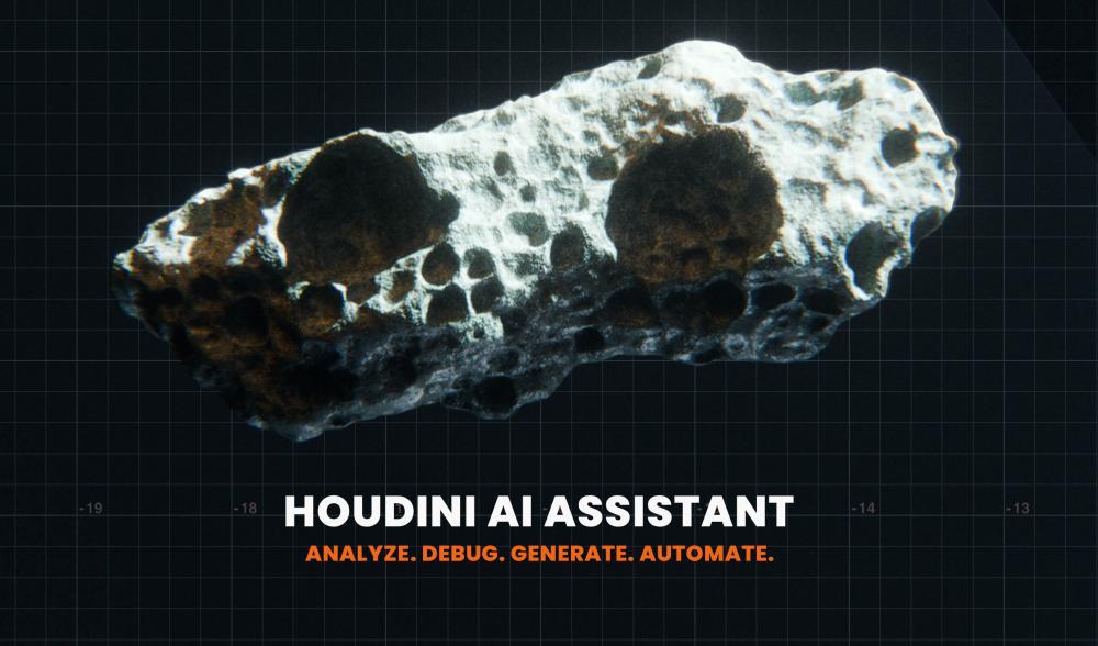
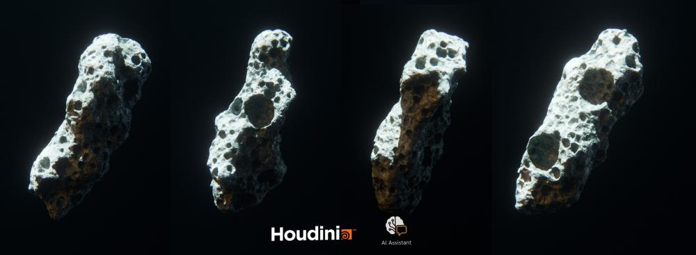
What if you could turn a simple prompt into a working Houdini HDA? In this demo, I use Houdini AI Assistant to generate a procedural Asteroid Generator in minutes. Houdini AI Assistant: https://rart.gumroad.com/l/HoudiniAIAssistant Instead of spending hours building node networks from scratch, the assistant helps speed up the process by generating the structure, parameters, and procedural logic from a prompt. In this video, I show: Prompt to HDA workflow AI-generated procedural asteroid setup Node-by-node inspection of the generated network Parameter tweaks and improvements Final result after just a few minutes This is not just a generic chatbot. Houdini AI Assistant works inside Houdini and helps with analyzing, debugging, generating, and automating procedural workflows. If you are learning Houdini, building tools, or trying to move faster in production, this is exactly the kind of workflow that can save a huge amount of time. Try Houdini AI Assistant here: https://rart.gumroad.com/l/HoudiniAIAssistant Thank you for all the support and feedback it really helps me improve the tool. More updates and demos are coming soon.

 1 point
 -
More or less procedural way. tennis_ball_spinning_v01.hipnc tennis_ball_spinning_v01.hipnc
 1 point
 -
Sony Pictures Imageworks is located on the unceded traditional territory of the Musqueam, Squamish, and Tsleil-Waututh First Nations. We are committed to respecting traditional lands, and working with communities towards reconciliation. Sony Pictures Imageworks Canada Inc. 658 Homer St Vancouver, BC V6B 0T5 Sony Pictures Imageworks is an Academy Award®-winning visual effects and animation studio known for photoreal live-action visual effects, dynamic creature and character animation, and full-CG features. Role Review: We are looking to expand our development team dedicated to enhancing our Creature Effect, Crowds, Environment, and FX tools and workflow. We are looking for a highly proficient Technical Engineer to focus on the development and implementation of robust, high-performance, and domain-specific procedural toolsets using SideFX Houdini. This role requires strong technical leadership and the ability to work effectively with minimal supervision alongside a Lead Software Engineer or Architect. The ideal candidate thrives in a fast-paced production environment where priorities can shift quickly. What You’ll Be Doing: Design, develop, and implement scalable procedural systems and workflows within Houdini for various departments (FX, Creature, Crowds, Environments). Create, maintain, and optimize robust Houdini Digital Assets (OTLs), ensuring stability, ease of use, and adherence to production standards. Extend the core pipeline by developing, integrating, and supporting tools that manage data flow, asset publishing, and version control. Collaborate closely with artists (Creature, FX, Lighting) to gather requirements and troubleshoot technical issues, providing support for both in-house and commercial tools. Partner with engineers across other teams (Shading, Lighting, Rendering) to ensure seamless integration of procedural assets into the overall rendering and compositing pipeline. Document tools and workflows thoroughly for use by the wider artistic and engineering teams. Required Technical Experience & Skills: 3-5+ Years of professional experience in developing procedural workflows and tools in a VFX, Animation, or Game production environment. Demonstrated knowledge of the Houdini environment, including tool creation, optimization, and workflow techniques. Strong proficiency in Python and VEX for writing efficient, custom nodes, and tool wrappers. Proven experience developing and supporting production pipeline tools and asset delivery. Experience leveraging the Houdini API and other DCCs like Katana. Strong grasp of 3D math, linear algebra, and data structures as applied to geometry processing and simulation. Strong verbal and written communication skills, with a collaborative approach to problem-solving. Capable of delivering on multiple competing priorities with little supervision. Preferred skills: Applies curiosity and judgment to identify broader or systemic issues and recommends creative approaches that address wider issues. Documented experience with desktop application development using PyQt/PySide to create custom user interfaces. Experience with C++ for high-performance plugin development. Experience with data science, machine learning, or complex simulation techniques (e.g., fluid dynamics, cloth) in a production context. Bachelor’s or Master's Degree in Computer Science, Digital Media, or a related technical field. The anticipated base salary for this position is within the range of $100,000.00/yr - $120,000.00/yr CAD (up to $150K for Senior candidates). The final compensation package will be commensurate with the candidate's professional experience, technical interview performance, and specific alignment with our team's requirements . Benefits are per company policy: which include healthcare, tuition reimbursement, RRSP's, Sick and Vacation leave, standard increases as applicable. The actual base salary offered will depend on a variety of factors, including without limitation, the qualifications of the individual applicant for the position, years of relevant experience, level of education attained, certifications or other professional licenses held, and if applicable, the location of the position. We value unique perspectives, and want diverse, unique talent to work with us. We encourage candidates from all identities to apply. *Sony Pictures Entertainment is an equal opportunity employer. We evaluate qualified applicants without regard to race, colour, religion, sex, national origin, disability, age, sexual orientation, gender identity, or other protected characteristics. Job Posting Link: https://www.imageworks.com/job-postings/43761 point
-
ATLANTIS ANIMATION is an animation studio based in the heavenly Canary Island of Tenerife. A combination of creative talent and technology definitely distinguishes us as a different studio to produce high quality animated series and feature films. We produced the sensational series Tara Duncan and Miraculous Ladybug season 5, both broadcasted on Disney Channel and Disney +. We are now getting ready for an absolutely new captivating project, the series 'Messi and the Giants', produced by Sony Music Vision, Sony Pictures Television Kids and Leo Messi Management, and broadcasted by Disney. An epic saga where a young boy named Leo is transported from his home in Argentina into a fantastical alternate universe. If you love animation challenges and unexpected adventures, and if you feel you have that special inner magic spark, we want to hear from you! Job Description: We're seeking a skilled and passionate Mid+ to Senior level Lighting TD to join our growing team for the upcoming series Messi and the Giants. The Lighting TD works closely with Lighting Artists within the team to deliver high-quality, optimized lighting renders for animated projects. You will be responsible for optimizing lighting and render settings using Arnold, ensuring both visual quality and performance. This role includes developing tools for the lighting department using Python within a USD-based pipeline. All tools created should support production workflows and contribute to a smooth and efficient production process. Therefore, it is essential that you are able to design and develop tools that are robust, efficient, well-documented, and easy to use for other team members. - Type of contract: Fixed-term Employee contract. - Location: 100% On-site in Tenerife. Remote work won't be possible for this specific position. Main Responsibilities: Technical Problem Solving & Tool Development: Diagnose and resolve complex technical issues related to lighting and rendering. Develop, maintain, and optimize tools, scripts, and workflows to automate tasks and improve efficiency within the lighting department. Troubleshoot technical issues such as render noise, long render times, and memory usage in a modern path-tracing renderer Workflow & Pipeline Integration: Collaborate with the Pipeline team and other departments (Look Development, Compositing, FX) to ensure seamless integration of lighting tools and processes within the broader production pipeline. Look Development Support: Work closely with Look Development and Surfacing artists to ensure shaders and assets behave correctly within lighting and color pipeline requirements. Complete assigned tasks within established deadlines, following direction from Supervisors and Leads. Maintain organized, clean, and well-documented files and scripts, ready for downstream use and internal documentation (e.g. Wiki pages). Requirements: Proven experience working as a Lighting TD in the TV animation industry. Ability to deliver high-quality lighting renders under tight deadlines. Strong understanding of USD-based pipelines and experience collaborating with multiple departments. Solid knowledge of lighting fundamentals and industry-standard tools. Strong understanding of color spaces, bit depth, and lighting data representation, including ACES. Ability to script using Python. Strong understanding of physically based rendering. Good knowledge of rendering efficiency and optimization techniques. Proven experience with Arnold Experience using production tracking tools such as ShotGrid (Flow). Excellent communication skills and ability to work effectively in a collaborative team environment. High attention to detail. Fluent in English (spoken and written). Ability to work on-site at our studio in Tenerife. A valid EU/Spanish work permit is required. Nice to have: Experience with Qt Experience working with Nuke Experience in shading.1 point
-
Small update on minimal surfaces using the poisson equation and some more modern nodes. minimal_surface.hip1 point
-
@ellietarrant me just playing," more like some Strange Crystal" need tweaking, with Rock Shader you can find (Please investigate and in the Future post file with your approach also) that Shader here https://www.sidefx.com/tutorials/as-cold-as-icewith-copernicus/
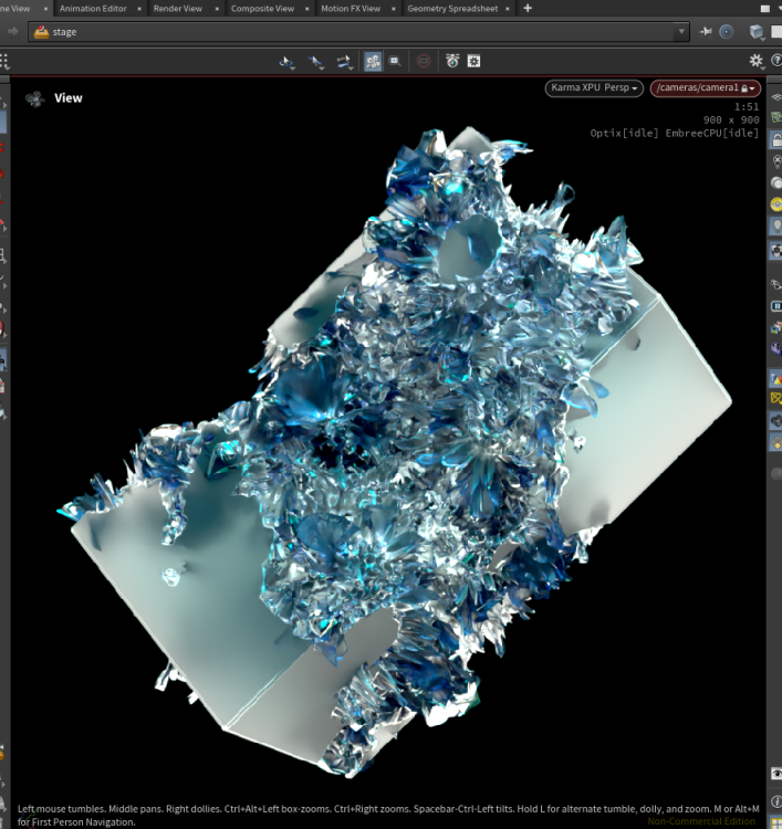 1 point
 -
There are so many nice example files on this website that I am often searching for. I wanted to use this page as a link page to other posts that I find useful, hopefully you will too. This list was started years ago, so some of the solutions may be dated. Displaced UV Mapped Tubes Particles Break Fracture Glue Bonds Render Colorized Smoke With OpenGL Rop Moon DEM Data Creates Model Python Script Make A Belly Bounce Helicopter Dust Effect Conform Design To Surface Benjamin Button Intro Sequence UV Style Mapping UV Box and Multiple Projection Styles Ping Pong Frame Expression Instance vs. Copy (Instance Is Faster) Particle Bug Swarm Over Vertical and Horizontal Geometry Rolling Cube Rounded Plexus Style Effect Pyro Smoke UpRes Smoke Trails From Debris Align Object Along Path Fading Trail From Moving Point Swiss Cheese VDB To Polygons Get Rid Of Mushroom Shape In Pyro Sim A Tornado Ball Of Yarn Particles Erode Surface Unroll Paper Burrow Under Brick Road Non Overlapping Copies Build Wall Brick-By-Brick FLIP Fluid Thin Sheets Smoke Colored Like Image Volumetric Spotlight Moving Geometry Using VEX Matt's Galaxy Diego's Vortex Cloud Loopable Flag In Wind Eetu's Lab <--Must See! Wolverine's Claws (Fracture By Impact) Houdini To Clarisse OBJ Exporter Skrinkwrap One Mesh Over Another Differential Growth Over Surface Blazing Fast OpenCL Smoke Solver [PYTHON]Post Process OBJ Re-Write Upon Export Rolling Clouds Ramen Noodles Basic Fracture Extrude Match Primitive Number To Point Number Grains Activate In Chunks Fracture Wooden Planks Merge Two Geometry Via Modulus Fill Font With Fluid DNA Over Model Surface VDB Morph From One Shape To Another Bend Font Along Curve Ripple Obstacle Across 3D Surface Arnold Style Light Blocker Sphere Dripping Water (cool) Exploded View Via Name Attribute VEX Get Obj Matrix Parts eetu's inflate cloth Ice Grows Over Fire Flying Bird As Particles DEM Image To Modeled Terrain Pyro Temperature Ignition Extrude Like Blender's Bevel Profile Particles Flock To And Around Obstacles BVH Carnegie Mellon Mocap Tweaker (python script) Rolling FLIP Cube Crowd Agents Follow Paths Keep Particles On Deforming Surface Particle Beam Effect Bendy Mograph Text Font Flay Technique Curly Abstract Geometry Melt Based Upon Temperature Large Ship FLIP Wake (geo driven velocity pumps) Create Holes In Geo At Point Locations Cloth Blown Apart By Wind Cloth Based Paper Confetti Denim Stitching For Fonts Model A Raspberry Crumple Piece Of Paper Instanced Forest Floor Scene FLIP pushes FEM Object Animated Crack Colorize Maya nParticles inside an Alembic Path Grows Inside Shape Steam Train Smoke From Chimney Using Buoyancy Field On RBDs In FLIP Fluid Fracture Along A Path COP Based Comet Trail eetu's Raidal FLIP Pump Drip Down Sides A Simple Tornado Point Cloud Dual Colored Smoke Grenades Particles Generate Pyro Fuel Stick RBDs To Transforming Object Convert Noise To Lines Cloth Weighs Down Wire (with snap back) Create Up Vector For Twisting Curve (i.e. loop-d-loop) VDB Gowth Effect Space Colonization Zombie L-System Vine Growth Over Trunk FLIP Fluid Erosion Of GEO Surface Vein Growth And Space Colonization Force Only Affects Particle Inside Masked Area Water Ball External Velocity Field Changes POP particle direction Bullet-Help Small Pieces Come To A Stop Lightning Around Object Effect Lightning Lies Upon Surface Of Object Fracture Reveals Object Inside Nike Triangle Shoe Effect Smoke Upres Example Julien's 2011 Volcano Rolling Pyroclastic FLIP Fluid Shape Morph (with overshoot) Object Moves Through Snow Or Mud Scene As Python Code Ramp Scale Over Time Tiggered By Effector Lattice Deforms Volume Continuous Geometric Trail Gas Enforce Boundary Mantra 2D And 3D Velocity Pass Monte Carlo Scatter Fill A Shape Crowd Seek Goal Then Stop A Bunch Of Worms Potential Field Lines Around Postive and Negative Charges Earthquake Wall Fracture Instance Animated Geometry (multiple techniques) Flip Fluid Attracted To Geometry Shape Wrap Geo Like Wrap3 Polywire or Curve Taper Number Of Points From Second Input (VEX) Bullet Custom Deformable Metal Constraint Torn Paper Edge Deflate Cube Rotate, Orient and Alignment Examples 3D Lines From 2D Image (designy) Make Curves In VEX Avalanche Smoke Effect Instant Meshes (Auto-Retopo) Duplicate Objects With VEX Polywire Lightning VEX Rotate Instances Along Curved Geometry Dual Wind RBD Leaf Blowing Automatic UV Cubic Projection (works on most shapes) RBD Scatter Over Deforming Person Mesh FLIP Through Outer Barrier To Inner Collider (collision weights) [REDSHIFT] Ground Cover Instancing Setup [REDSHIFT] Volumetric Image Based Spotlight [REDSHIFT] VEX/VOP Noise Attribute Planet [REDSHIFT] Blood Cell Blood Vessel Blood Stream [REDSHIFT] Light Volume By Material Emission Only [REDSHIFT] Python Script Images As Planes (works for Mantra Too!) [REDSHIFT] MTL To Redshift Material [REDSHIFT] Access CHOPs In Volume Material [REDSHIFT] Mesh Light Inherits Color [REDSHIFT] Color Smoke [REDSHIFT] FBX Import Helper [REDSHIFT] Terrain Instancer Height Field By Feature Dragon Smashes Complex Fractured House (wood, bricks, plaster) Controlling Animated Instances Road Through Height Field Based Terrain Tire Tread Creator For Wheels Make A Cloth Card/Sheet Follow A NULL Eye Veins Material Matt Explains Orientation Along A Curve Mesh Based Maelstrom Vortex Spiral Emit Multiple FEM Objects Over Time Pushing FEM With Pyro Spiral Motion For Wrangle Emit Dynamic Strands Pop Grains Slope, Peak and Flat Groups For Terrains Install Carnegie Mellon University BVH Mocap Into MocapBiped1 Ramp Based Taper Line Fast Velocity Smoke Emitter Flip Fill Cup Ice Cubes Float [PYTHON]Export Houdini Particles To Blender .bphys Cache Format [PYTHON] OP UNHIDE ALL (opunhide) Collision Deform Without Solver or Simulation Mograph Lines Around Geometry Waffle Cornetto Ice Cream Cone Ice Cream Cone Top Unroll Road Or Carpet Burning Fuse Ignites Fuel or Painted Fuel Ignition Painted Fuel Combustion Small Dent Impact Deformation Particle Impact Erosion or Denting Of A Surface Helicopter Landing Smoke And Particles Radial Fracture Pieces Explode Outwards Along Normal Tangent Based Rocket Launch Rolling Smoke Field Tear/Rip FLIP (H12 still works in H16) Rain Flows Over Surface Rains Water Drip Surface Splash Smoke Solver Tips & Tricks Folding Smoke Sim VEX Generated Curve For Curling Hair Copy and Align One Shape Or Object To The Primitives Of Another Object (cool setup) A Better Pop Follow Curve Setup FEM Sea Cucumber Moves Through Barrier Fracture Cloth Smoke Confinement Setup Merge multiple .OBJ directly Into A Python Node Blood In Water Smoke Dissipates When Near Collision Object Whirlpool Mesh Surface Whirlpool Velocity Motion For FLIP Simple Bacteria Single Point Falling Dust Stream Flames Flow Outside Windows Gas Blend Density Example Localized Pyro Drag (smoke comes to a stop) Granular Sheet Ripping Post Process An Export (Post Write ROP Event) Corridor Ice Spread or Growth Set Velocity On Pieces When Glue Bonds Break Water Drops Along Surface Condensation Bottle Grains Snow or Wet Sand Starter Scene A Nice Little Dissolver Turn An Image Into Smoke Fading Ripples Grid Example Stranger Things Wall Effect Face Through Rubber Wall [PYTHON]Create Nurbs Hull Shelf Tool [PYTHON] Ramp Parameter [PYTHON] On Copy OF HDA or Node Select Outside Points Of Mesh, Honor Interior Holes Sparks Along Fuse With Smoke Umbrella Rig Melt FLIP UVs Tire Burn Out Smoke Sim Flip or Pyro Voxel Estimate Expression Motorcycle or Dirt Bike Kicks Up Sand Particles Push Points Out Of A Volume [PYTHON]Cellular Automata Cave Generator Punch Dent Impact Ripple Wrinkle VEX Rotate Packed Primitive Via Intrinsic Kohuei Nakama's Effect FLIP Fluid Inside Moving Container Particles Avoid Metaball Forces FLIP Divergence Setup FLIP Transfer Color Through Simulation To Surface Morph Between Two Static Shapes As Pyro Emits Constraint Based Car Suspension Pyro Smoke Gas Disturbs Velocity Wire Solver Random Size Self Colliding Cables Fast Cheap Simple Collision Deform CHOP Based Wobble For Animated Character Slow Motion FLIP Whaitewater Avoid Stepping In Fast Pyro Emission Fast Car Tires Smoke FLIP Fluid Fills Object Epic Share Of Softbody/Grain Setups (Must see!) Balloon, Pizza, Sail, Upres Shirt, Paint Brush Create Pop Grain Geometry On-The-Fly In A DOPs Solver Varying Length Trails VEX Based Geometry Transform Determine Volume Minimum and Maximum Values Grain Upres Example Animated pintoanimation For Cloth Sims Batch Render Folder Of OBJ files Vellum Weaving Cloth Fibers Knitting Kaleidoscopic Geometry UV Image Map To Points Or Hair Color Particles Like Trapcode Particular Flat Tank Boat Track With Whitewater Orthographic Angle Font Shadow Select Every Other Primitive or Face? Printer Spits Out Roll Of Paper Unroll Paper, Map, Plans, Scroll Simple Vellum L-System Plant Basic Cancer Cell 2D Vellum Solution Vellum Animated Zero Out Stiffness To Emulate Collapse Whitewater On Pre Deformed Wave [PYTHON] Menu Callback Change Node Color Extruded Voronoi With Scale Effector Multi Material RBD Building Fracture House Collapse Spin Vellum Cloth Whirlpool Vortex Trippy Organic Line Bend Design Logo Based Domino Layout Delete Outer Fracture Pieces, Keeping Inside Pieces UV Mapped Displaced Along Length Curly Curves Slow Particle Image Advection Nebula Saw Through VDB Like Butter Fuel Based Rocket Launch With Smoke Fuel Based Rocket Launch With Smoke [upres] Deform Pyro Along Path Bend Pyro Gas Repeat Solver With RBD Collision Raining Fuel Fire Bomb City Video Tutorial Pyro Cluster Setup (Animated Moving Fuel Source) [PYTHON] Mantra .MTL File Reader (creates new materials) Pyro Dampen By Distance FLIP Fluid Sweeps Away Crowd Ragdoll Gas Repeat Solver X-Men Mystique Feather Effect Camera Frustum Geometry Culling Vellum Extrude Shape Into Cloth Wire Web Constraint Setup Pyro Smoke Font Dissolve "Up In Smoke" Helicopter Landing With Vellum Grass and Dust or Smoke Another Thin Sheet Fluid Setup Color Rain Drops Over Surface Dual Smoke Object Wand Battle Custom GasDisturb node (easy to use) Hair Driven Grass Example File Pyro Smoke With Masked Turbulence Align High Resolution Mesh With Low Resolution RBD Simulation Streaky Portal Effect Height From Luma Cracking Glass Dome, Fracture VEX Noise Types FLIP Waterwheel Fracture Brick Wall Using UVs Vellum Stacked Torn Membranes Terrain Topographical Line Curves Prepare RBD Fracture For Unreal Alembic Export Growing Ivy Solver Fix For Intermittent FLIP Surfacing Issue Extensive RBD Fracturing Thread With HIP Files Peter Quint's Pop Streams Particle Example Fracture Geometry To Release Flip Fluid Inside Procedurally Reverse Normals Vellum Culling Voronoi Shape To Shape Transition Animated Scattering Accessing Parametric UVs On A Surface Organic Hallways/Corridors Through A Mesh Smoke Particle Dissolve Along One Axis Expanding Vellum Rings That Collide With One Another Read, Fetch, or Get SOP Attribute Inside Of DOPS Broad Splash When Object Enters Water Blendshape Crowd Example [PYTHON] Replace Packed Intrinsic Geometry From Another Source Rip/Tear Part Of Paper To Reveal And Roll Up After Effects Text Styles Cabling Mesh Surface Hanging Wires Or Cables Use Python Inside a Font Sop Brand Accurate Textures Using Karma XPU hScript asCode Microscopic Hair USD Attribute Equivalents For Preview Shader (i.e. Cd mangle) Vellum Peel Effect SOP Pyro Control Field Gas Disturbance Repair Geometry Self Intersection FLIP Follows Curve Long Winded Guide To Houdini Instancing Disable Simulations On Startup Tutorial HIP Library Use Google To Discover Attached HIP Files Useful Websites: Tokeru Houdini Houdini Vex Houdini Python Houdini Blueprints FX Thinking Rich Lord HIP Files iHoudini Qiita Ryoji Toadstorm Blog Eetu's HIP Of The Day Video Tutorials: Peter Quint Rohan Dalvi Ben Watts Design Yancy Lindquist Contained Liquids Moving Fem Thing Dent By Rigid Bodies Animating Font Profiles Swirly Trails Over Surface http://forums.odforce.net/topic/24861-atoms-video-tutorials/ http://forums.odforce.net/topic/17105-short-and-sweet-op-centric-lessons/page-5#entry127846 Entagma Johhny Farmfield Vimeo SideFX Go Procedural1 point
-
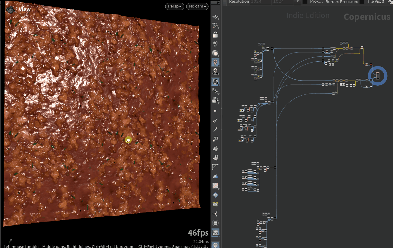
I'm working on a personal project starring a pasta monster, I had to create a bolognese sauce for it. I tought it could be fun for others (at least to look around in COPs). Have fun with it! bolognese_cops.hiplc I followed this article and tried to replicate what he did in Substance Designer, but using COPs. Copernicus is indeed amazing!! https://80.lv/articles/making-fusilli-pasta-material-with-substance-3d-designer-houdini The ingredients:
 1 point
 -
I think I have found the perfect solution. This seems 100% correct. Takes into account the camera motion as well. screen_space_velocity_2.hiplc
 1 point
 -
velocity damping in solver can also help. sometimes when too manny geo is falling ontop of each other, collision passes needs to be increased... i know now what i ll have for dinner1 point
-
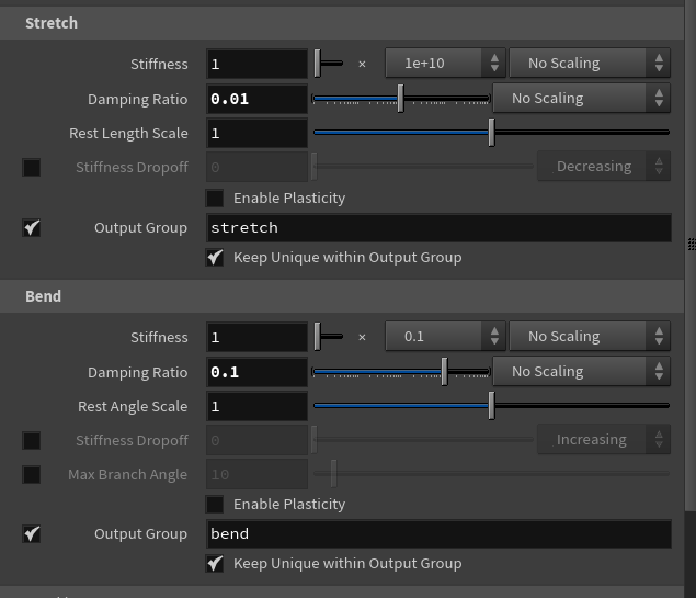
Ha! Found it. Bend Stiffness and Damping Ratio is the key, and I also used 5 substep.
 1 point
 -
Hi, yeah I tried that originally, but only did set "nextid", forgot about the "id" so I was getting -1 as id on the first frame haha, thanks!1 point
-
Hi Alain I have the great pleasure to tell you that this is working beyond dreams I changed very few things, only the pinning of each ends of the curve; the dynamics were set absolutely right for this type of material. Cooking time is almost insignificant and the animation plays back at 12fps with the polywire This setup would even handle a lot more stress than shown here. I am thinking of doing a spray paint nozzle and have this thing paint stuff or write.. I am still considering the best approach.. attribute transfer, Pyro spread temp attr.. If you wish to join this little project, you are more than welcome Many Thanks Vellum_Helix_03.hipnc
 1 point
 -
Here is a splash sequence .bgeo.sc exporter that Juraj posted a while back. With this HIP you can quickly generate small splash sequences to copy to your impact points. jt_rain_rnd.hipnc
 1 point
 -
Or maybe the existing Volume Arrival Time SOP? You do need to go to volumes and back which is a bit of an inconvenience. ee_shortest_path_arrivaltime.hip
 1 point
 -
Ok, here's a simple implementation of an age field for pyro ee_pyro_age_mask.hip1 point
-
Just connect Ng instead of N whenever applicable in Vops. Sometimes it's easier to overwrite N in displacement shader (pluging Ng into N output), so that the whole surface shader sees facetednormals without manual rewiring. hth, skk. btw. The way of faceting polygons in SOPs is to use VertexSOP->Cusp Normals. It just creates a vertex normal attribute without unwelding your geometry.1 point