Search the Community
Showing results for tags 'grid'.
-
Hello, I need to create a radial gradient on a gird, my idea was to use a addpoint, to add a point at the center of the grid. Then connect it to a point wrangle and calculate the distance between it to the other points. Although, I am not sure on how to execute this idea. Thanks!
-
-
Hello Guys, Is there someone who understand python in houdini? Because i don't I wanna trying remake this > Video I read one interview where Albert Omoss talking he rebuild this code from Processing to Python in Houdini, but i dont find any tips how to make it or how i can rebuilt GeneticGrid.mp4
-
Hello and welcome to this post. Synopsis: In nature, we see a phenomenon called tropism (the way a leaf orients itself towards the sun). I need help building a rig that will simulate this effect. These are the objectives: Create a source object acting as the reference point for tropism Get the leaf to orient itself in relation to the source Additional challenge: It would be ideal to shade the front and back face of the leaf with a different texture. What is a neat VOP setup which would simulate this? Here is a basic HIP file to begin messing around with. leafShading_Orient.hipnc
-
Hi! I am a bit newbie, sry. I have to flip particles of a grid by 360 degrees, controlled by a null swiping through the grid. Here is my solution so far. Unfortunately I can not solve the 360 degree flip properly. It would be good to have some randomization of flip axis on it too. I wuld like to make some randomization on the scale too. Could you give me some hints on it , or perhaps edit my scene , please? Thanks in advance. Robert Flip particles on grid_10.hip
-
Hey Houdini legends, I am trying to create the centre of this flower. I have created all the tint disc flowers but now need to clone them onto a radial hexagon grid sort of thing. I have made a sphere and managed to get a honeycomb grid with the divide sop but I need the polys to get larger towards the outside and the pscale to reflect the scale of the prim. Any Ideas?
-
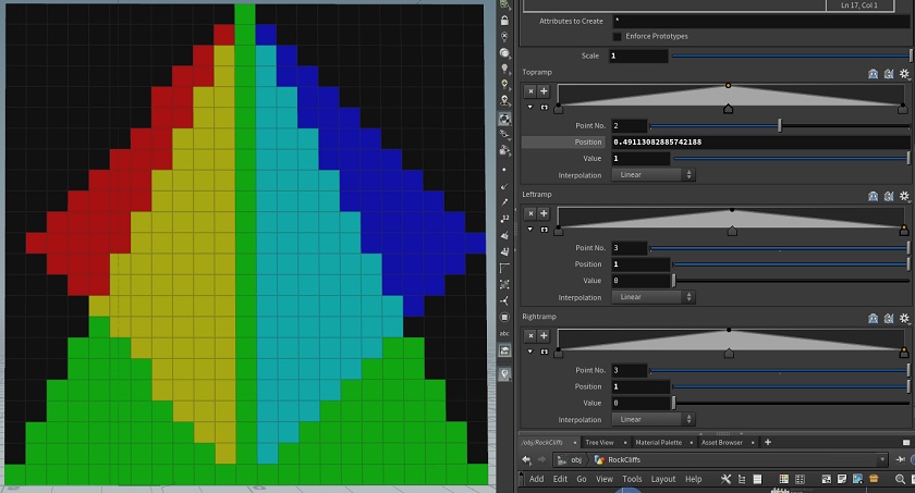
Hi all, Im looking to control the colors on a grid ( YZPlane) in VEX to create a mask (will be used to create a group of the un-masked area), My approach is to use relpointbbox for the position and 3 chrand's for each side profile, Im looking to see if someone has done something similar. My current solution (and for those interested) is fairly simple but gives good control. vector bbox = relpointbbox(0,@P); float Right = chramp('RightRamp',bbox.y); float Left = chramp('LeftRamp',bbox.y); float Top = chramp('TopRamp',bbox.z); //Init to 0 v@Cd = 0; //Top Ramp if(bbox.y<Top ) @Cd.g=1; //Left Ramp if(bbox.z<Left/2+.5 && bbox.z>.5 ) @Cd.r=1; //Right Ramp if(bbox.z > (1-Right)/2 && bbox.z<.5 ) @Cd.b=1;
-
hey guys. im pretty new to houdini. im trying to move particles in space but in a grid like fashion. similar to the old windows screensaver with these pipes. right now i try to find the highest velocity vector and would like to set every vector thats lower than the highest to 0. but i cant find a solution on how to do that. help would be much appriciated. cheers, jamin
-
I'd want to change from Tom Hardy's to Venom's. Can you let me know if you have any good tutorials?
-
- changing image
- grid
-
(and 1 more)
Tagged with:
-
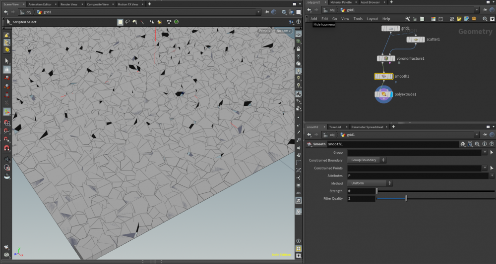
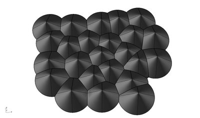
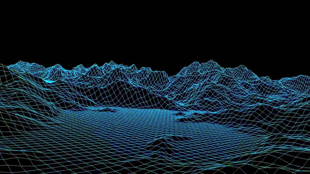
I'm trying to make a plane of simple rolling hills using voronoi. I don't want realistic terrain, just basic smooth curved circular overlapping mounds with phong material. I think what I need to do is generate flattened spheres that extend outwords from the center of each cell, but I haven't been able to locate the right node to do that. I've tried grid -> voronoi fracture -> smooth -> extrude but it can't get anything that looks rounded. What am I doing wrong here? Why does everything I attempt look so "rocky" like broken glass? First image is what I have, others are examples of my intended look (more or less).
-
Hi ! I'm pretty newb in Houdini and after a few months of training myself I'm trying now to create my own setup. Here I want to move points from a grid randomly to x or y position. A random value is generated every seconds to change the direction and the axis of the next move of each point. I already understand it must be completed with a solver sop, but I can't understand why amplitude is multiplied when I move points into the solver. I need to scale down a lot the movement. Anyone can tell me why ? Or just take a look to my project file here. Could be nice to have a little help to understand this issue. Thanks Dot_Grid.hiplc
-
Hi All! I'm wondering if anyone has run into this and found a good solution, it's been popping up in my low-to-mid viscosity sims for a while. Perhaps I'm missing something stupidly obvious? Collision geo/field are fine and the interface between fluid and collision object looks great before turning on viscosity, then I get these grid artifacts that are tough to get rid of. Reducing Surface Extrapolation way down in Volume Collisions helps but doesn't completely remove the artifacts. Also, using a high slip-on-collision value helps, but I usually don't want the sliding behavior with sticky viscous fluids. Reducing Grid Scale reduces the relative grid size and helps too, but the artifacts are still there, just smaller. Attached file is somewhat of a worst-cast example, just curious if other folks have dealt with this before. I know I can run some post-sim tweaks to clean up the collision surface intersection, but I've also noticed that the artifacts reveal themselves on the outer surface of the fluid if it gets thin enough, which is not so easy to fix... 01 - viscosity disabled 02 - viscosity enabled 03 - viscosity enabled, surface extrapolation 0.01 Thanks in advance for any help/ideas!! --Dave DStewart_FLIP_ViscousCollisionStepping.hip
-
So I'm working on creating a grid with specific attributes or perhaps groups. So say "1" generates a Cube "2" generates a Sphere and "3" generates a Torus, going up to 9. So my idea is that I can type out a grid like so: 1;1;1;3;3;3;2;2;2 2;2;2;3;3;3;1;1;1 3;2;1;3;2;1;3;2;1 1;2;3;1;2;3;1;2;3 3;2;1;2;3;2;1;2;3 This would then divide the 5x9 grid into groups based on the numbers. Is there an elegant way of achieving this in VEX/Python? This could also work as a point cloud but it would need to have constant spacing between the numbers and control over the size in units of the grid. As a follow up this would be great if I could use this as a weaving pattern with splines. So in this case "1" would mean: on top, "2" would mean under: and "3" would mean: extra high. Though this should work if we get the rest to work as is. Any help with this would be appreciated.
-
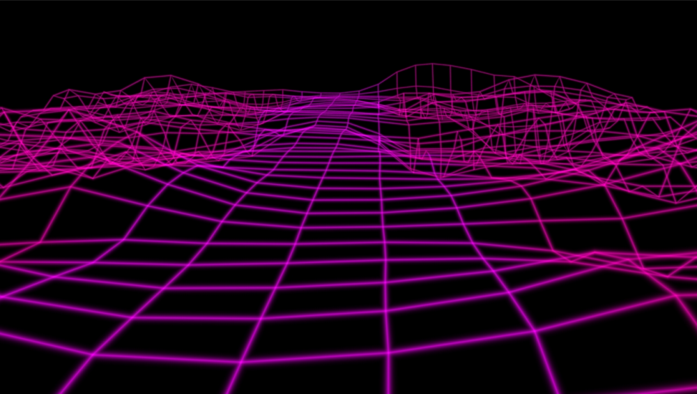
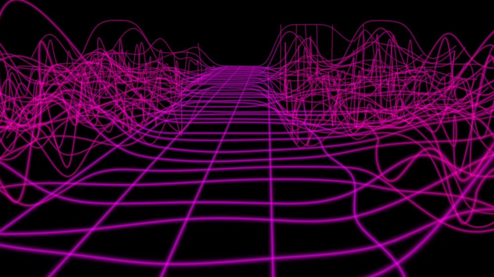
Hi there, I'm totally a noob using Houdini and I'm trying to figuring out how to achive this classic retro look. I can imagine there's some basic options ie: compositing some textures with the wireframes or creating thin polywires to create actual meshes for this edges. I also found this interesting post abut glowing points. I almost get to look I want playing with similar custom shaders, specially because I wanted to try with Nurbs in these lines, but of course it just deals with points, so I should somehow matte the grid faces itself to oclude edges behind other edges. It does make any sense this approach? Should I layer different shaders for the points or edge primitives and other one for the polygon faces itself? Would like to credit Thomas Helze for the FastGlow used in this tries above. Since this is a typical effect from all the times, I wanted also to know if anybody could just bring here some historical background about it, I'm feeling that the principles behind that look had changed a bit every time retro neon sci fi gets trendy again... And of course, please feel free to send me back to the QuickStart guides and all that... just wish you understand it's my first time posting here and you know, I'm feel like a totally stupid noob asking loud a stupid question at the end of a masterclass...
-
Hey guys, Lately I've been using the grid in my network pane (tools > show grid), and I always snap my nodes to the intersection points so it's all nice and pretty. But every so often, multiple times a day, and usually when I re-open a scene, all the nodes will be nudged off, maybe ~1/4 grid space in a given direction. It's as if the grid is being drawn in a slightly different location. Obviously it's not a huge deal to just select all the nodes and scoot them over, but it gets a little redundant having to do it in every network, and kind of defeats the purpose of having a neat grid. I'm wondering if anyone else notices this or knows of an RFE for it, or if it's just me... Thanks!
-
Hi I am using a texture that I got from a height field output node. For simplicity's sake I removed my terrain shader and simply assigned a principled shader with texture displacement enabled. You can't really notice this unless the grid is really large (which it needs to be for me), but these grid lines appear in the render for some reason. They are not the edges/ resolution of the grid being deformed. I did notice that if I go to obj level and change the shading quality to a high enough value, the grid eventually disappears. Why is this? Whats weird is that these grids dont appear if I render the heightfield directly. Thaknks
-
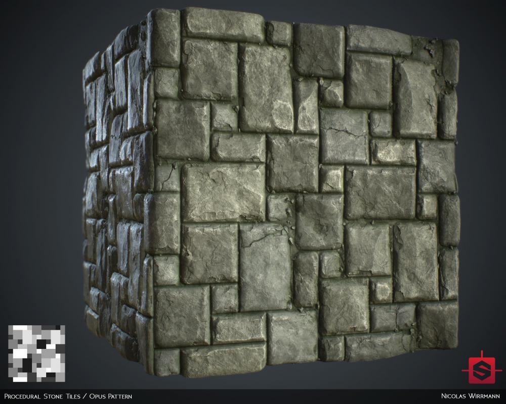
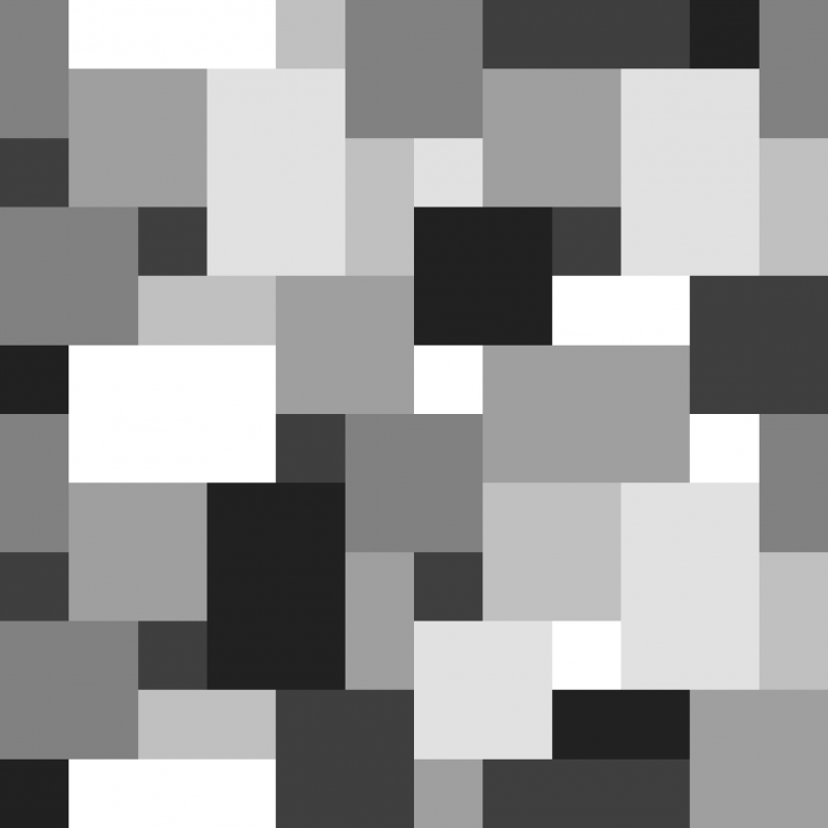
Hi Houdini hive-mind new here (sort of) looking for some advice on how I might be able to create a grid where the cells are arranged in an opus pattern. I have a cell of a minimum dimension (lets say 200x200), I want to be able to have the other cells multiple dimension of that in x and y. (400x800, 600x400 or even 200x2000 for example). Crucially there are no L shaped/tetris type arrangments. Im fairly sure it involves making a grid of cells with the minimum size, and making random selections to delete and build bigger patches, but not sure the best way to go about it without creating odd shapes. I've reached my intelligence limit, and I defer to clever folk here for any kind suggestions (or of course, solutions posted elsewhere) Thanks
-
Hey magicians, I've been trying to do some pattern stuff inspired by Ehsan Parizi, but I can't get my head on how to do it. Here are some Ehsan examples And this is what I did so far lol I know this is probably not the best way, im stuck to rotate them in certain axis like he did, any tips on how to create this different types of patterns will be really helpful. Attached is my file. Thanks! gridtest.hip
-
Hi guys, How do I make a knife always be perpendicular to grid it is cutting?
- 1 reply
-
- knife
- perpencidular
-
(and 1 more)
Tagged with:
-
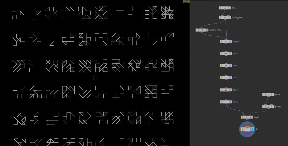
Hi all, I'm trying to make a glyph generator based on a 3x3 crossed grid. This is where I have got to so far. The way I've created this is pretty rough. I made a grid, divided it, flipped it, merged the results, fused, converted to wireframe, assigned random colour for primitives, delete by colour, stamped with copySOP. Instead of converting the edges to a primitive, i would prefer to assign a random attribute to the edges and delete them on that basis. But my knowledge has hit a wall as edges aren't really attributable according to the geospreadsheet. Further, I need to figure out a way to identify when a 'X' happens and delete one of the edges. Maybe I could fix this further up the tree by stamping a grid which randomly flips a divided cell (rather than flipping the whole grid and merging+fusing them). If anyone has any pointers let me know, I will also attach the hip too. Hope I make sense! Cheers. glyph.hip
-
Hi, How do I change the subdivisions on the grid in houdini? The option is greyed out. Thanks in Advance
-
C-plane display different in persp and in ortho
Bulgrozz posted a topic in General Houdini Questions
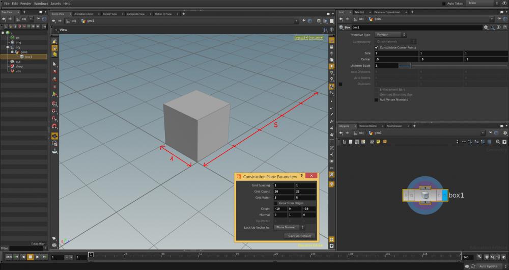
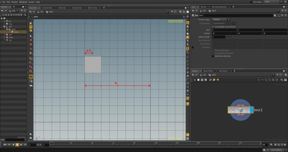
Hi All, I've set up my C-plane to display lines every 1 unit and major lines every 5 units (screenshot CP1). It works perfectly in persp but in the other views (top, front, etc.) the display is back to lines every 0.5 unit and major lines every 4 units (screenshot CP2). What did I missed? Thanks- 2 replies
-
- contruction plane
- grid
-
(and 1 more)
Tagged with:
-
Hi, guys. I get a problem maybe it was be asked before, but i can't find any tips. There is a grid polygon and i add a line on it by add SOP. Is it any way split the grid to two part by the line even the vertex number was not right. I can split it by polySplit or Clip, Break SOP, but they were not flexible enough. Any help will be appreciated! Thanks. grid_split.hip
-
Hi, I want to know if it's possible to have an object attribute outputted as file or in a ROP Net node. I have a 1024x1024 grid right now. Each point on the grid represent a pixel. This grid has many attribute and I would love to render a map of all these attribute. I know and tested to copy each attribute to the Cd attrib and render it. It works but I wonder if there is a simpler way. A node for instance that would not need a camera or would not need to copy the attribute to render to the Cd attrib. Ideally I would like to have a render node that renders the top view of an object given attribute. Thx! C
-
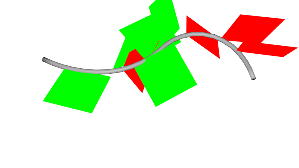
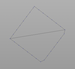
Good day, I'm looking for a simple way to convert a line or a curve in a curve composed only with right angle edges. I have try to use Fuse SOP in Snap/Grid mode but this gave me 45 degrees angle too. Any idea?









ChristianSirois-GoogleChrome.jpg.a228044b6cd2e012efcde0dd49940e0c.thumb.jpg.e2b7b5454974ab34cfc9980b8c517f4d.jpg)