Search the Community
Showing results for tags 'transform'.
-
 My whole end goal is essentially just trying to take a Transform SOP's pivot rotation (visually shown in the viewport as the transform pivot handle) and extract it as a vector. This way I can then apply this rotation pivot vector to future transform SOPs to effectively copy the rotation pivot across. Note that I'm not talking about the rotation of the geometry, I'm talking about the pivot since I've already figured out the geometry rotation successfully. At first this sounds simple but, unless I've gone down the wrong path, it seems to be very difficult. This is because the pivot's rotation is affected by three different parameters in the Transform SOP. When you rotate with the Transform SOP, it has three different vector parms to enter rotation data for: pre-rotate, pivot rotate, and rotate. If you play around with them, you'll realize the node combines them in order like this: pre-rotate --> pivot rotate --> rotate. The resulting rotation is then applied to the geometry/pivot. That's all handy dandy and all. But I for the life of me can't get my VEX to mimic this behavior using matrix math. This is down to that pesky order in which rotations are combined. Currently my logic is to relative reference the 3 rotation parms into a detail wrangle, convert them to matrices, multiply them with eachother in the order explained above, then finally convert the resulting matrix back into a euler vector. But rotating some geo with this new vector shows an incorrect rotation in certain cases (again, all down to the order in which the rots are used). I can tell its incorrect since I'm just doing a direct comparison of the viewport handle I'm calculating (visualized on a Transform SOP) to a second Transform SOP that's being used as my ground truth. Basically after studying transform matrices and how to combine them for rotation calculations I'm getting stuck in this instance and I simply can't figure this out anymore (my brain is too small). But maybe there's just a simpler way to extract the euler rotation of the pivot handle. Can anyone give me any ideas, or even better some simple working solution/VEX for this problem that I can go off of? Much appreciated, thanks everyone.
 -

I need help to extract the scale from a Matrix...
Masoud posted a topic in General Houdini Questions
Hello guys, From a transform matrix attribute (which includes "Transform", "Scale" and "Rotation" values), how can I extract only the "SCALE" component, and then apply it, to the geometry? I mean I don't want the Translate and Rotation of that matrix. I tried the cracktransform() VEX function. If it's a right way, I don't know how to apply that extracted scale, to the geometry: v@t; v@r; v@s; cracktransform(XFORM_SRT, XFORM_XYZ, {0,0,0}, 4@localtransform, @t, @r, @s); Thanks for helping. -
Hi guys, I'm looking for the simplest way to scale a geometry, using VEX (by an attribute) and I would like to be able to define the pivot position, too. I tried these codes. It works but I don't need the other transform parts (like Position, Rotation, and ...): vector t=chv("Translate"), r=chv("Rotation"), pr=chv("pivot_rotation"); vector p = v@myPivot; vector s = f@myScale; matrix transform = maketransform(0,0,t,r,s,p,pr); @P *= transform; There is a VEX function: scale(matrix &m, vector scale_vector); But I don't know how to use it. Thanks for helping.
-
This one has me stumped - is it possible to move and offset (not retime!) Spectrums and corresponding Foam caches post sim? I'm rendering an Ocean in Karma but need to transform and offset it at render time. For previews I am timeshifting and transforming the Ocean Preview Grid with applied Spectrum, moving it around in camera to art direct where a wave is along with its Whitewater foam cache etc. Works great, can easily take a long cache, offset it, move the whole ocean closer or farther from cam as per supervisors needs without having to resim etc. Realized at render time, simply doing the same to the Spectrum wont work. Thought to offset the Time in Spectrums but that of course just made totally new patterns in the waves. And cant move it with a Transform really can you? I am worried the only way is to bake the geo then move and offset? To be clear, I dont want to retime, or change the look or speed of the sim at all. I simply want to take the cached foam and its corresponding ocean (which works when the spectrum is baked to geo and then moved), and move it in space, and offset its cache a few 100 frames so Karma renders it correctly. Cheers!
-
 Hello, I'm bad at math so I tried google but still havent found anything relevant So technically I want to move object along camera path like Maya's image plane If anyone has idea please give me clue for it, thanks
 -
i have a library of packed primitives with a unique name attribute that i import, copy and transform, and mirror. I need to extract these final transforms to export a json. Is there a way to do that? Usually i have the orient attribute that helps me to generate a 3x3 transform but in this case i don't have any other attributes other than the position. extract_transform.hip
-
Hello, I have been trying to create a Tet soft body simulation with a glue constraint to itself to fake stretching and breaking. I am however failing at multiple steps. 1. The solve takes forever, it keeps on detangling thingies 2. the transforms don't work. bread_3.hipnc SD_BaseMesh_v001.obj
-
The gist of the effect I need done is this. I need this Logo to start out fractured into a ton of pieces and off screen in all directions then I need the pieces to kindof suction in towards the screen center where they come together to form the full logo My current workflow is basically run the sim backwards (the logo starts off fully formed and i explode it outwards, then reverse the RBD sim) The problem when I reverse the sim I get a very harsh stop on each piece once the piece gets to its start pose I fix this sort of by running a jiggle or lag CHOP motion effect over the points after i reverse the sim, adding some overshoot to the sim so it overshoots the rest pose and then settles back into the rest pose the issue is now i get intersections with the pieces. Was hoping someone might know how i could maybe run another simulation on top of the reversed sim? Like have it follow the same motion but adjust for self collisions?
-
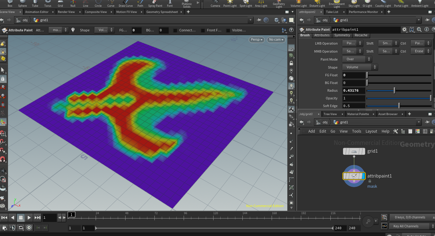
I'm trying to move points on a grid, with the transform affecting the points according to the values stored per point in a "mask" attribute defined by an Attribute Paint node. As in, on the grid in the attached image, I'd like the points in red (1.0 "mask" value) to move the full value of a subsequent Transform node, points in purple (0 "mask" value) to not move at all, and points in between to move based on their own "mask" value. Say, a point with 0.4 "mask" would move (0.4*Transform). To me, this seems like a simple request/operation, but I can't sort out how to actually make Houdini do it. I've tried a subsequent Transform node but couldn't sort out how to make it apply selectively per point, modified by the "mask" value. I can make a group that is limited to points with nonzero values and move that, but that's a boolean sort of selection, and I can't use the "mask" values to modulate the effect the Transform has for a nice falloff. I then tried a For Each loop that applied to each point, and was able to get each point to move with a simple Transform within the loop, so I can use that to nudge around *all* the points the same distance, but I can't get it to use the "mask" value, and I'm not sure how to get the For Each loop to only look at the points that have non-zero values (understanding that multiplying by a zero "mask" value would give no translation as desired, but sometimes it's nice to not have the cooking process even look at those to start with). I tried "10*@mask" and "10*P.mask" in the within-the-For-Each-Loop-Transform's translate channels to try to use the "mask" value, but those didn't work. I *know* I'm missing something obvious, as I'm still learning all of this, but is there a simple solution to this sort of thing? It seems like a simple request, but I can't find hide nor hair of a clean, easy way to handle this, and a complex solution is out of my understanding to date. Thank you!

-
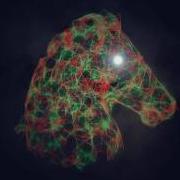
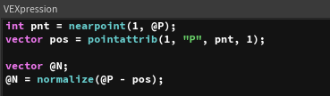
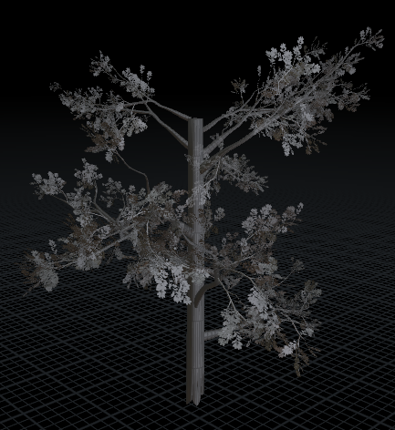
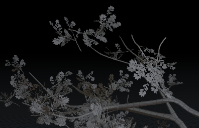
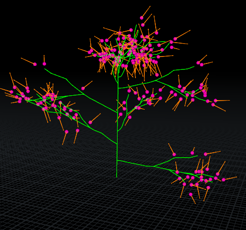
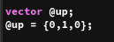
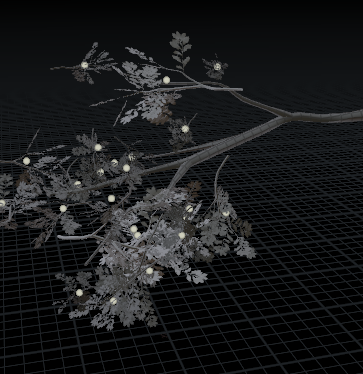
Hello all, I have a built a rig that allows for the dynamic simulation of trees. I was able to define an instance point which is offset from the trees branches. This enables the copying of a packed leaf primitive onto the point. The next step is to update the rotation of the packed primitive. It seems like the copy to points has defaulted to using the z-axis (vector pointing in the {0,0,1} direction). The tree includes a central wire which captures the deformation as it moves through space. I have been able to construct a normal by using the following logic: Using a leaf point find the closest point of the wire compare point positions (@P{leaf point} - @P{wire point}) normalizing the compared vector and setting an @N attribute VEX CODE However, when using this @N (normal) on the copy to point the leaf geometry picks up this @N (built above in vex) and discards the desired z-axis vector of {0,0,1}. Here is a diagram demonstrating the results. Figure 1 - This is the result of the vex code written above (visualized left), notice when using the vex code normal the leaf is unable to correctly orient itself to the point (visualized right). The custom vex code normal is required to guide the orientation and the tree deforms. This is shown in the following .gif animation. Figure 2 - A .gif animation demonstrating the updating normal as the tree deforms I have also tried adding an @up vector to see if that resolves the issue, however, that route is also producing me undesirable results. I have though about using some form of quaternion or rotational matrix, however, I am currently studying these linear algebra concepts and I need time and guidance before fully understanding how to apply the knowledge in Houdini. Could someone please offer guidance in this regard. I am working on supplementary .hip file which should be posted shortly. Warm regards, Kimber
-
 Hi folks, I have searched around, but similar questions are either unresolved or unanswered. Hopefully now in 2019 we have a simple solution to this simple issue. I have used the Extract Transform node in Houdini, which gave me the position and rotation of my object. Prior to that, I have simmed a Rigid Body object, and used this node to replace it with a higher-resolution version for my render. Now I wish to do the same in Maya. I have a high-res model of my rigid body, and it would be a waste to export each frame in alembic. It would be great to export a simple Null with a position and rotation attribute or something like that, and constraint my object to it in Maya. It sounds simple, but I can't do it. Attaching a ROP FBX or alembic to the ExtractTransform node produces the files, but they're just a locator without any attributes in Maya. How can I get this set-up to work, or what are the alternatives? Thank you.
 -

Transform a transform sop UI Handle by Matrix
Djangotron posted a topic in General Houdini Questions
Hello, I'm trying to stick a transform sop's UI handle to a point or prim without loosing control of the pivot functionality of the transform node. I've bundled this into an HDA and promoted the handle and used a point expression to get a position from the point I've got the rotation via another point expression and some VEX to unpack the matrix I use both of these expressions on the transform handles pivot translate and pivot rotate parameters This gives me the expected behavior with exception to the pivot being overwritten. Is there a way that I could 'parent' this handle or use the pre-translate/rotate for this problem? The only option I see for this right now is a custom python handle but I'm just wondering if there is anyone more creative than I who could suggest an alternative way around this problem. -
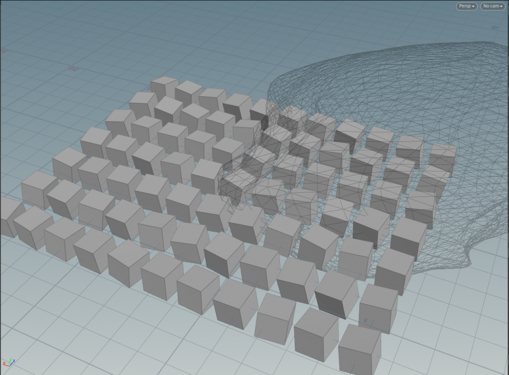
Hello, I have noob question. I want these boxes to weaken their random rotation as they move away from the sphere. But I don't know how to set the weakly by distance at vex... Is there anyway for to do that? thank you Rotate By Distance.hipnc
-
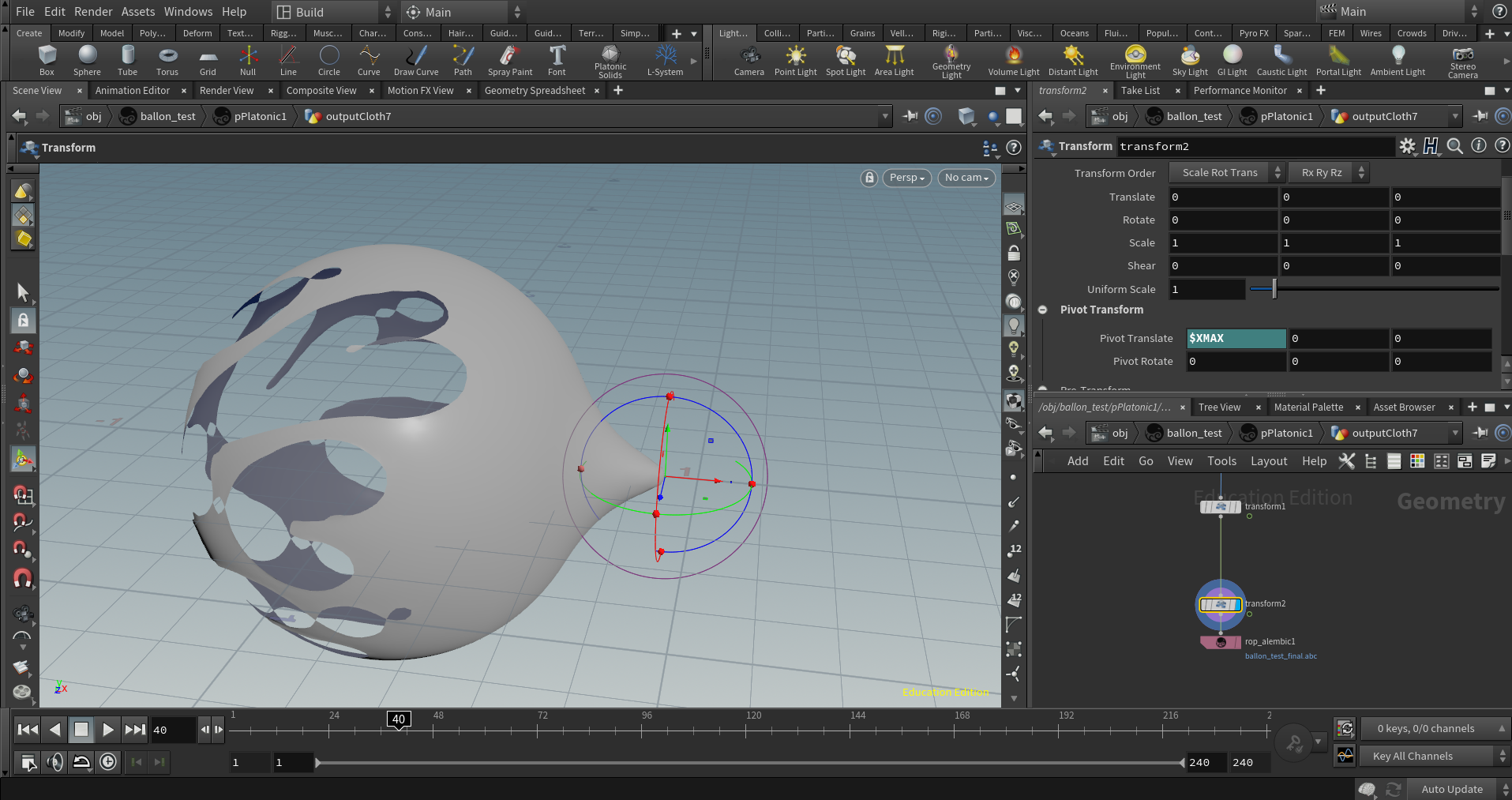
 Hi, this is my first post, sorry in advance if I get something wrong. So I have an alembic file which comes from a nCloth simulation in Maya where I used a tearable constrain to break the cloth and a transform constrain to pull it in one direction. I imported the alembic in Houdini to polish and refine it. I also used a transform node with $XMAX in the pivot transform to scale the whole thing after the simulation is finished (since it needs to scale to 0 after the simulation is over). Now onto my question, how can I keep the pivot (found with $XMAX) at the centre of the world at every frame? so that the simulation appears to "start and grow" from the pivot itself? In the .hip file you will see two transform nodes ad the end, in the first one I used the $XMAX to scale from one end and achieve the "disappear effect", the second transform just has $XMAX because I was testing how to do it. I attached my .hip file but unfortunately, the alembic is too heavy for my internet connection (which is really bad), sorry about that.. Thank you in advance for you time ballon_alembic_cleanup.hipnc
-
Hey, I am currently building an HDA with python viewer states and I want to display an image/grid in the upper left corner of the viewport. This is what I currently use to move the grid to the current viewport postion. viewport = hou.ui.curDesktop().paneTabOfType(hou.paneTabType.SceneViewer).curViewport() cam = viewport.viewTransform() hou.parmTuple('/obj/geo1/transform1/t').set(cam.extractTranslates()) hou.parmTuple('/obj/geo1/transform1/r').set(cam.extractRotates()) I also transform the grid in the negative z direction afterwards. This results in the image beeing in the center of the viewport. But I'm not sure how I can move the image to the corner of the viewport and keep it in the correct postion when the viewport is beeing resized. Maybe with the viewport.viewportToNDCTransform() or viewport.mapToWorld() methods. But I couldnt figure out how. I found a promising vex based result here:https://youtu.be/7UuVhbTRcew?t=1890 string cam = chs("camera"); vector bb = relbbox(0,@P); vector4 crop = chp("crop"); bb.x = fit(bb.x, 0, 1, crop.x, crop.y); bb.y = fit(bb.y, 0, 1, crop.z, crop.w); bb.z = chf("zoffset"); @P = fromNDC(cam,bb); But this one requires a camera node and I'd rather have this logic in the python states if possible. Thanks
-
A while ago I used some very simple Matrix multiplications to bring geometry, that is positioned anywhere in space, back to the origin and from there, back to its original position. Maybe anybody here can help me remember? I think I created a world space transformation Matrix, called it myMatrix, and then multiplied it by its reverse to transform geo to the origin. In order to translate the geo back, I just multiplied by myMatrix...is that possible or am I getting something wrong? (Not in fromt of a Houdini right now) Anyway, how do I get the world space transformation matrix for an object positioned anywhere in world space, for example for some geo that came into my scene as an ABC from Maya? Lookattransform in VOPSOPs? Thanks for your hints and patience.
-
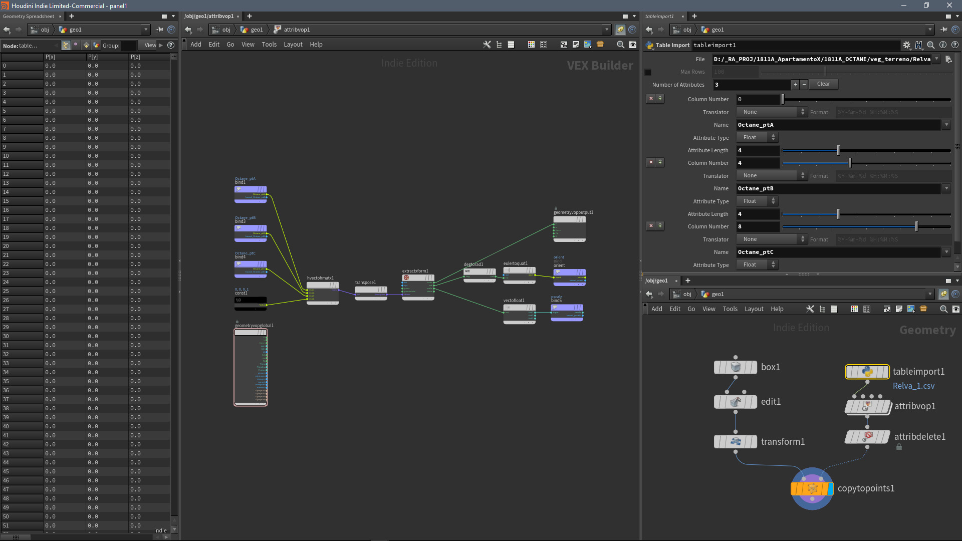
Hi, I'm writing this post more as a note, rather than doubt. I was reading about Table import and found a way to do a tool I wanted some time ago. It's an translation between Octane Standalone CSV and Houdini matrices - 3x4 -> transposed 4x4. For me it is useful to recover old scatters from lost files / different programs and be able to edit them. I'll leave it here in case it is useful for someone else. Cheers! M

-
Trying to find some info on applying quaternion rotations without using the copytopoints @orient point attribute. I build my quaternion, and then I'm stuck on doing two things: -Applying the rotation to an unpacked object and a packed object I've tried the rotate by quaternion VOP with unpacked geo and the makeinstancexform for packed geo and nothing seems to work this way... I've done some research but didn't find anything usefull (outside of copytopoints @orient). Can some one point me in the right direction?
-
 Hey, I simulated low res RBD pieces and am using a transform Pieces node to apply the position / rotation back onto the highres geo. To get the orientation / pivot for the template points input of the transform pieces node I used a "dop import" node which is set to create points to represent objects. But I had to bake out the RBD objects and animate on top of em in Maya and brought em back to houdini. I made sure the name attribute is exactly the same as on the highres geo again and packed it and currently just using an attribute wrangle to delete all prims so I only have points left. But those only come with P and name. How can I get the correct orientation / pivot back to align my highres geo correctly using the Transform Pieces node? Thanks guys!
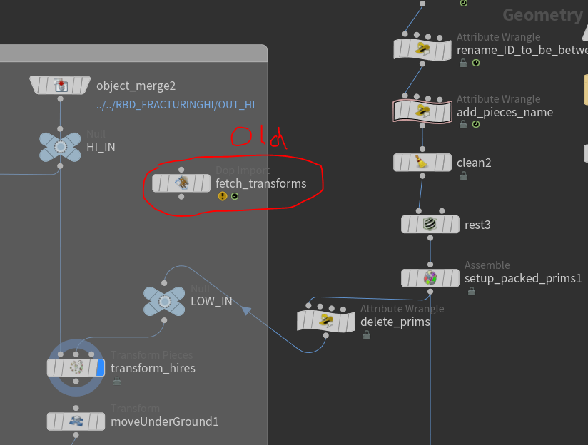
-
The effect from 15 seconds. What should I do? array animation???? rigid??? popnet????.... I don't know how.
-
hello guys. ive been bashing my head against the wall and read through way too many forums now. but i couldnt find something similar to my problem. Im trying to create for now a simple setup is to just break my glue constraints. The ball and colliding objects both have animation ( deforming). Now i do realize that my constraints get reconstrainted because of Overwrite with SOP option set to 1. however if i were to set it to 0 to only bring in the constraints on the first frame for the constraints to stay broken, the constraints would not be able to follow according to the animation of the ball, because it is rotating and changing position, leaving it very innacurate. So could anyone help me troubleshoot this? i think i have to somehow update the position and rotation of the constraints but i dont know how. I would provide a scene but it my scene is for a job. ive already tried matching position but there is rotation as well on the sphere, the resulting collision looks inaccurate as if its offseted broken_setup.mov broken_setup_position.mov
-
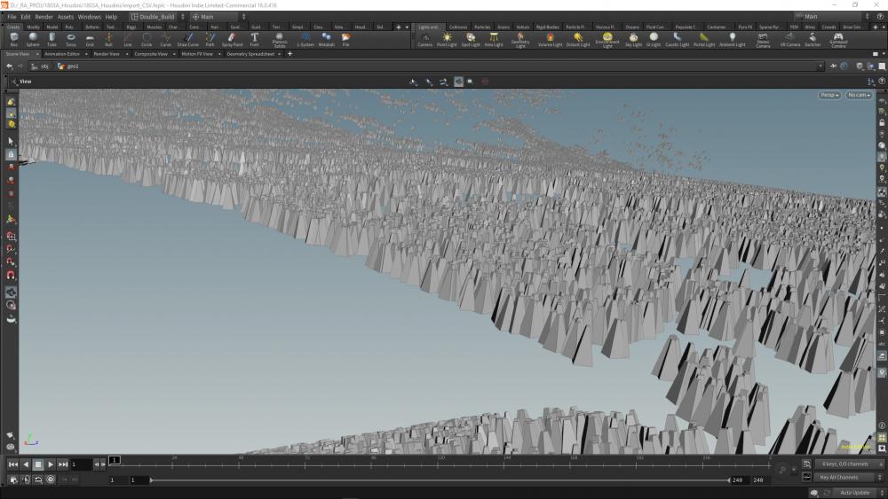
 I am working on a big destruction job and I’m trying to optimise our workflow as much as possible. my usual workflow: - cache a single frame of my fractured geo as packed fragments - import rbd sim and create point per rbd piece (dop import) then lighting would import these two caches and use transform pieces. This works well since we only cache a single frame of the fractured geo, and the cache for the rbd points is very small. however the geo is still written into the ifd file every frame, which can be quite large. So, is it possible to specify the geo needed for the whole sequence and then have mantra transform the geo at render time (the same as transform pieces). This would make the ifd’s tiny an alternative method is to write each fractured piece out as a separate file then copy empty packed disk primitves to the rbd points then use the unexpandfilename intrinsic to expand it at render time. This makes tiny and fast ifd files which is great but seems quite slow to render - probably because it has to pull so many files from disk (1000s of pieces).. is it possible to do the render time transform pieces approach or does anybody have a better method? (The two I’ve mentioned are fine I’m just trying to optimise it!)
 -
Hello all, I'm attempting to make an effect like this and am getting stumped if anyone had any ideas on how to approach it would be super helpful! Thanks.

-
Hi Guys, I'm trying to replicate COP workflow from Simon Holmedal, in the video below about 29:00 he folding UV coordinate VOPCOP filter... I can't make it work... Any Idea? Thanks.
-
Ran into an issue while learning DOPs. After having setup Vellum in SOPs I'm trying to import the setup in DOPs. At first everything is fine and dandy, but if there is a Transform added to the geometry on object level then only the GEO that's imported into DOPs network is updated. The Constraints are still in their original position. Is it possible to update Vellum constraint location when the object node is transformed? Adding a basic example file with the issue. test.hipnc